LUGGAGE COMPARTMENT DOOR OPENER SYSTEM Luggage Compartment Door Opener does not Operate
DESCRIPTION
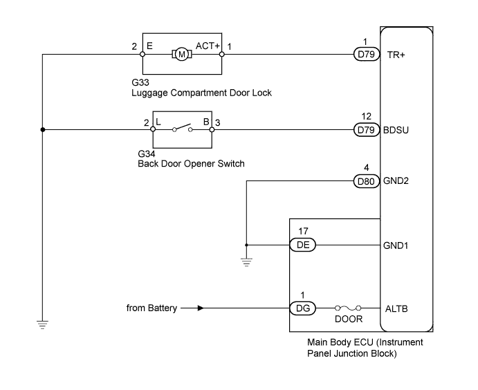
The main body ECU detects the condition of the back door opener switch.
WIRING DIAGRAM
INSPECTION PROCEDURE
Tech Tips
Inspect the fuses for circuits related to this system before performing the following inspection procedure.
PROCEDURE
-
PERFORM ACTIVE TEST USING INTELLIGENT TESTER
-
Select the Active Test, use the intelligent tester to generate a control command, and then check that the luggage compartment door lock motor operates Click here.
Main Body Tester Display Test Part Control Range Diagnostic Note Trunk and Back-Door Open Operate luggage compartment door latch release ON or OFF - Result Result Proceed to Luggage compartment door lock motor does not operate (door does not open) A Luggage compartment door lock motor operates (door opens) B
B 
READ VALUE USING INTELLIGENT TESTER (BACK DOOR OPENER SWITCH) Click here
A 
-
-
CHECK HARNESS AND CONNECTOR (MAIN BODY ECU - BATTERY AND BODY GROUND)
-
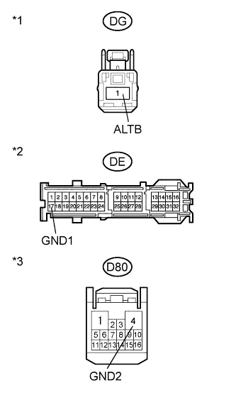
Text in Illustration *1 Front view of wire harness connector
(to Main Body ECU)
*2 Front view of wire harness connector
(to Main Body ECU)
*3 Front view of wire harness connector
(to Main Body ECU)
Disconnect the DG, DE and D80 ECU connectors.
-
Measure the voltage according to the value(s) in the table below.
Standard Voltage Tester Connection Condition Specified Condition DG-1 (ALTB) - Body ground Always 11 to 14 V -
Measure the resistance according to the value(s) in the table below.
Standard Resistance Tester Connection Condition Specified Condition DE-17 (GND1) - Body ground Always Below 1 Ω D80-4 (GND2) - Body ground Always Below 1 Ω
NG 
REPAIR OR REPLACE HARNESS OR CONNECTOR
OK
-
-
INSPECT LUGGAGE COMPARTMENT DOOR LOCK ASSEMBLY (DOOR LOCK MOTOR)

-
Remove the luggage compartment door lock assembly Click here.
-
Move the luggage compartment door lock to the lock position.
-
Apply battery voltage and check the operation of the door lock motor.
OK Measurement Condition Specified Condition Battery positive (+) → Terminal 1
Battery negative (-) → Terminal 2
Opens
NG
REPLACE LUGGAGE COMPARTMENT DOOR LOCK ASSEMBLY Click here
OK
-
-
CHECK HARNESS AND CONNECTOR (MAIN BODY ECU AND BODY GROUND - LUGGAGE COMPARTMENT DOOR LOCK)
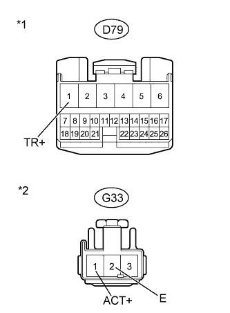
Text in Illustration *1 Front view of wire harness connector
(to Main Body ECU)
*2 Front view of wire harness connector
(to Luggage Compartment Door Lock)
-
Disconnect the D79 ECU connector.
-
Disconnect the G33 lock connector.
-
Measure the resistance according to the value(s) in the table below.
Standard Resistance Tester Connection Condition Specified Condition D79-1 (TR+) - G33-1 (ACT+) Always Below 1 Ω G33-2 (E) - Body ground Always Below 1 Ω D79-1 (TR+) - Body ground Always 10 kΩ or higher
NG
REPAIR OR REPLACE HARNESS OR CONNECTOR
OK 
REPLACE MAIN BODY ECU
-
-
READ VALUE USING INTELLIGENT TESTER (BACK DOOR OPENER SWITCH)
-
Use the Data List to check if the back door opener switch is functioning properly.
Main Body Tester Display Measurement Item/Range Normal Condition Diagnostic Note Back Door Open Handle SW Back door opener switch signal / ON or OFF ON: Back door opener switch on
OFF: Back door opener switch off
- OK Tester display changes according to operation of back door opener switch.
NG
INSPECT BACK DOOR OPENER SWITCH ASSEMBLY Click here
OK
REPLACE MAIN BODY ECU
-
-
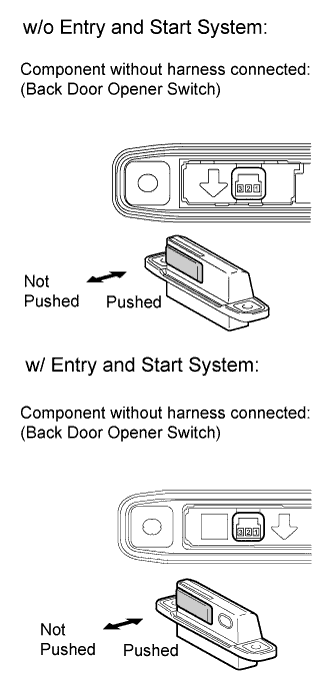
INSPECT BACK DOOR OPENER SWITCH ASSEMBLY
-
Remove the back door opener switch Click here.
-
Measure the resistance according to the value(s) in the table below.
Standard Resistance Tester Connection Switch Condition Specified Condition 2 - 3 Back door opener switch not pushed (Off) 10 kΩ or higher 2 - 3 Back door opener switch pushed (On) Below 1 Ω
NG
REPLACE BACK DOOR OPENER SWITCH ASSEMBLY Click here
OK
-
-
CHECK HARNESS AND CONNECTOR (BACK DOOR OPENER SWITCH - MAIN BODY ECU AND BODY GROUND)
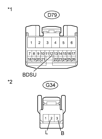
Text in Illustration *1 Front view of wire harness connector
(to Main Body ECU)
*2 Front view of wire harness connector
(to Back Door Opener Switch)
-
Disconnect the D79 main body ECU connector.
-
Measure the resistance according to the value(s) in the table below.
Standard Resistance Tester Connection Condition Specified Condition D79-12 (BDSU) - G34-3 (B) Always Below 1 Ω G34-2 (L) - Body ground Always Below 1 Ω D79-12 (BDSU) - Body ground Always 10 kΩ or higher
NG
REPAIR OR REPLACE HARNESS OR CONNECTOR
OK
REPLACE MAIN BODY ECU
-