FRONT SEAT ASSEMBLY (for Power Seat) REASSEMBLY

CAUTION:
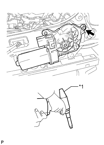
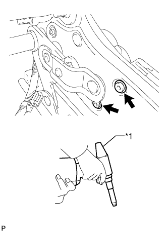
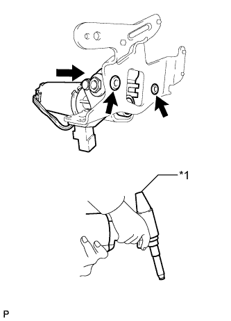
Wear protective gloves. Sharp areas on the parts may injure your hands.
Tech Tips
-
Use the same procedure for RHD and LHD vehicles.
-
The procedure listed below is for LHD vehicles.
-
Use the same procedure for the RH and LH sides.
-
The procedure listed below is for the LH side.
-
A bolt without a torque specification is shown in the standard bolt chart Click here.
-
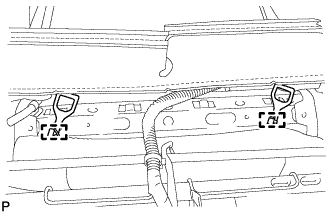
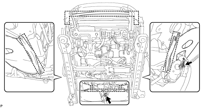
INSTALL NO. 2 REAR UPPER SEAT TRACK COVER
-
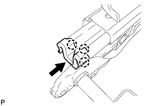
Attach the 3 claws to install the No. 2 rear upper seat track cover.
-
-
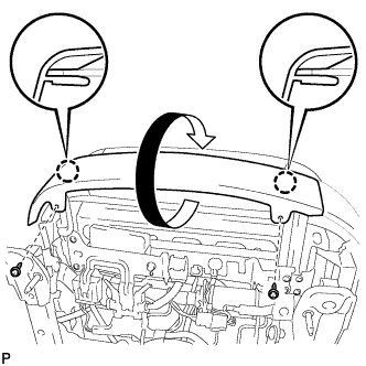
INSTALL REAR UPPER SEAT TRACK COVER
-
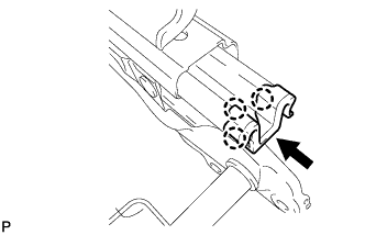
Attach the 3 claws to install the rear upper seat track cover.
-
-
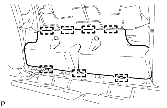
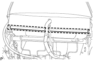
INSTALL SEPARATE TYPE FRONT SEAT CUSHION SPRING ASSEMBLY
-
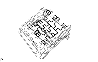
Attach the 8 hooks to install the separate type front seat cushion spring assembly to the front seat adjuster assembly LH.
-
-
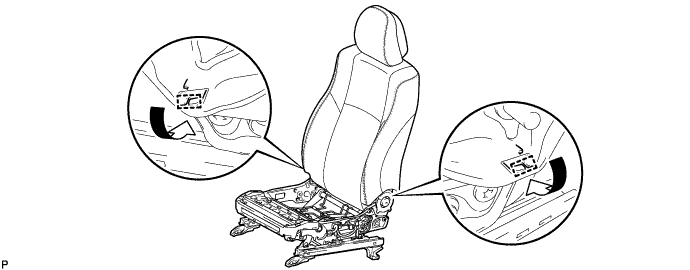
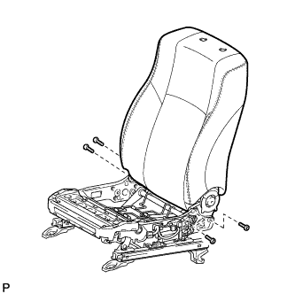
INSTALL FRONT SEAT ADJUSTER ASSEMBLY LH
-
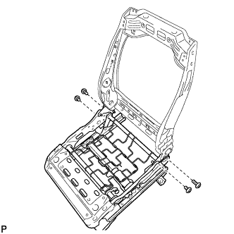
Using a T50 "TORX" socket wrench, install the front seat adjuster assembly LH with the 4 "TORX" bolts.
- Torque:
- 35 N*m { 357 kgf*cm, 26 ft.*lbf }
-
-
INSTALL FRONT SEAT INNER BELT ANCHOR BRACKET COVER LH
-
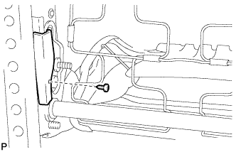
Install the front seat inner belt anchor bracket cover LH with the screw.
-
-
INSTALL FRONT SEAT LOWER CUSHION SHIELD LH
-
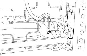
Install the front seat lower cushion shield LH with the screw.
-
-
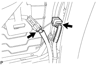
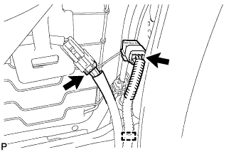
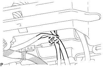
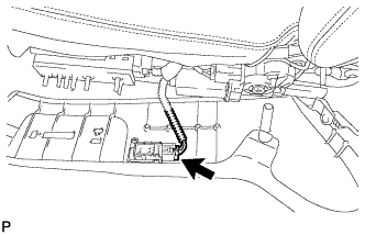
INSTALL FRONT SEAT WIRE LH
-
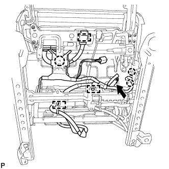
Attach the 3 claws to install the front seat wire LH.
-
Attach the 3 wire harness clamps and connect the connector.
-
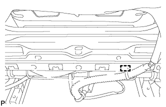
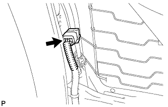
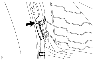
Attach the wire harness clamp.
-
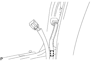
Attach the wire harness clamp.
-
-
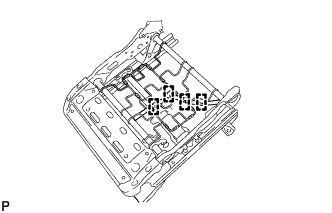
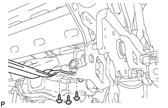
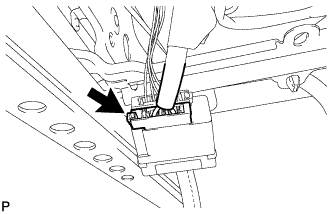
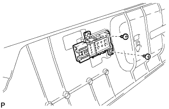
INSTALL POSITION CONTROL ECU ASSEMBLY (for Driver Side)
-
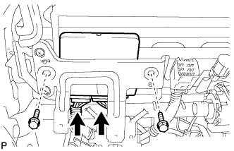
Install the position control ECU assembly with the 2 bolts.
-
Connect the 2 connectors.
-
-
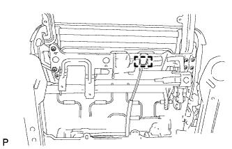
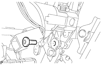
INSTALL SEAT CLIMATE CONTROL CONTROLLER LH
-
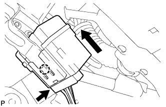
Attach the claw to install the seat climate control controller LH.
-
Connect the connector.
-
-
INSTALL POWER SEAT MOTOR ASSEMBLY (for Reclining)
-
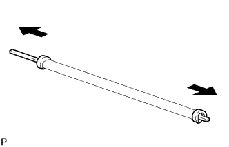
Remove the 2 holders together with the 2 inner reclining rods from the reclining rod.
-
Remove the inner reclining rod and push nut from the holder.
-
Remove the inner reclining rod and push nut from the holder.
-
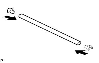
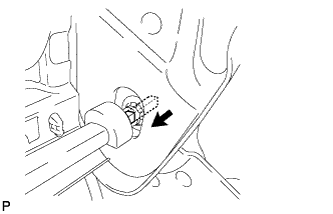
Install the 2 holders to the reclining rod.
-
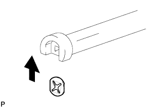
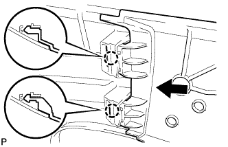
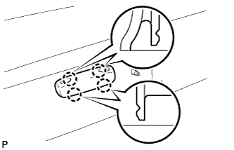
Install the push nut to the holder.
Note
Make sure the direction of the push nut is as shown in the illustration.
-
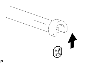
Install the push nut to the holder.
Note
Make sure the direction of the push nut is as shown in the illustration.
-
Clean the threads of the bolt for the power seat motor assembly with non-residue solvent.
-
Apply adhesive to the threads of the bolt for the power seat motor assembly.
Adhesive Toyota Genuine Adhesive 1324, Three Bond 1324 or equivalent -
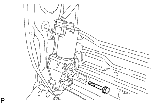
Temporarily install the power seat motor assembly with the bolt.
-
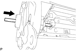
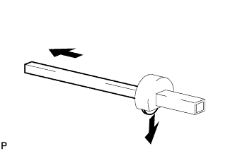
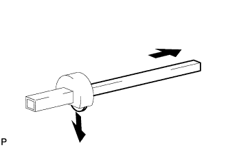
Push in the inner reclining rod as shown in the illustration.
-
Push in the inner reclining rod as shown in the illustration.
-
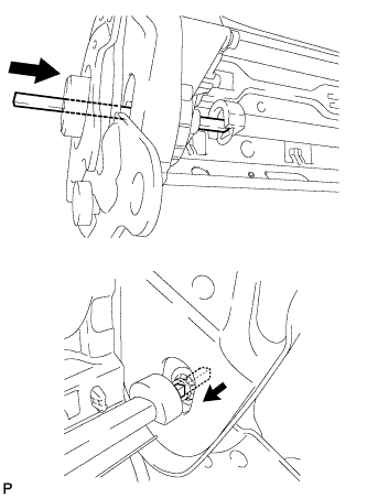
Push in the 2 inner reclining rods in alternating passes to install them
Note
Make sure that the holder does not interfere with the power seat motor assembly or front seatback frame.
-
Tighten the bolt.
- Torque:
- 5.0 N*m { 51 kgf*cm, 44 in.*lbf }
-
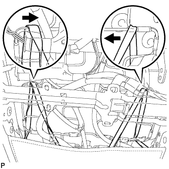
Attach the 8 hooks to install the seatback spring.
-
for Driver Side:
Connect the 2 connectors.
-
for Front Passenger Side:
Connect the connector.
-
-
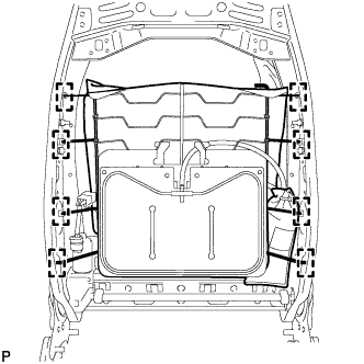
INSTALL FRONT SEAT AIRBAG ASSEMBLY LH
-
Install front seat airbag assembly LH with 2 new nuts.
- Torque:
- 6.0 N*m { 61 kgf*cm, 53 in.*lbf }
-
Attach the 4 harness clamps and connect the connector clamp.
-
-
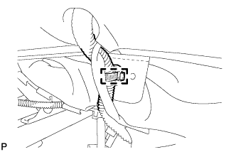
INSTALL LUMBAR SUPPORT ADJUSTER ASSEMBLY LH
-
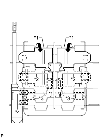
Attach the 2 hooks B to install the lumbar support adjuster assembly LH to the seatback spring.
Text in Illustration *1 Back Sheet *2 Hook A *3 Hook B *4 Cable Tie -
Install 2 new cable ties.
-
Return the 2 back sheets to their original positions and attach the 4 hooks A.
-
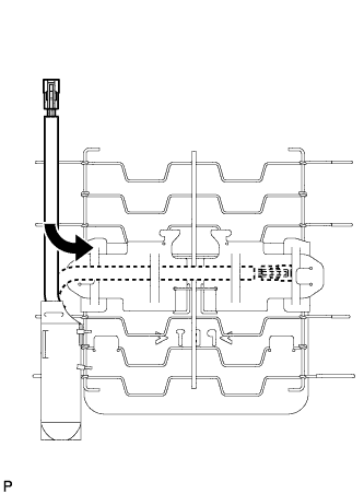
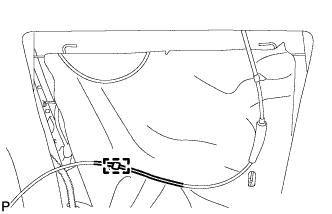
Return the wire harness to its original position as shown in the illustration.
-
Attach the 8 hooks to install the seatback spring.
-
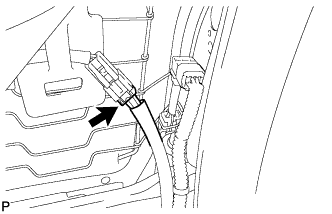
Connect the connector.
-
-
INSTALL FRONT SEATBACK HEATER ASSEMBLY
Note
When replacing either the front seatback heater assembly or separate type front seatback pad due to a malfunction, be sure to replace both of them with new parts.
-
Remove the peeling paper from a new front seatback heater assembly.
-
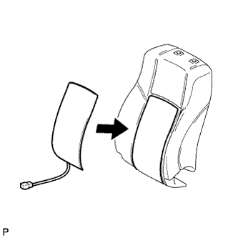
Install the front seatback heater assembly to a new separate type front seatback pad.
-
-
INSTALL SEPARATE TYPE FRONT SEATBACK PAD
-
Install the separate type front seatback pad.
-
-
INSTALL SEPARATE TYPE FRONT SEATBACK COVER
-
Attach the 2 hooks.
-
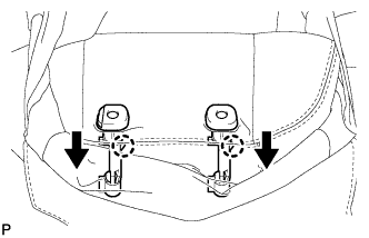
Attach the 2 claws to install the 2 front seat headrest supports.
-
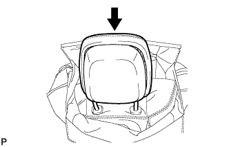
Install the front seat headrest assembly.
Note
Push in the front seat headrest assembly until the headrest lock engages.
-
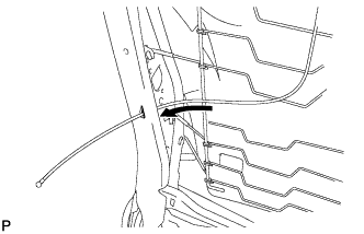
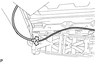
Pass the cable through the hole of the seatback frame.
-
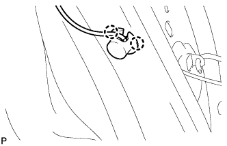
Attach the 2 claws to install the clip.
-
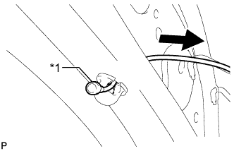
Text in Illustration *1 Cable End Pull the cable through the clip until the cable end reaches the clip.
-
Install a new cable tie.
-
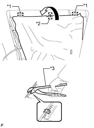
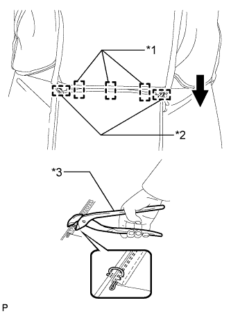
Text in Illustration *1 Hook *2 Hog Ring *3 Hog Ring Pliers Attach the 2 hooks and close the seatback mat.
-
Using hog ring pliers, install a new hog ring.
-
Attach the 2 claws to connect the cable to the active headrest lower unit.
-
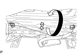
Attach the 2 claws to install the active headrest lower unit.
-
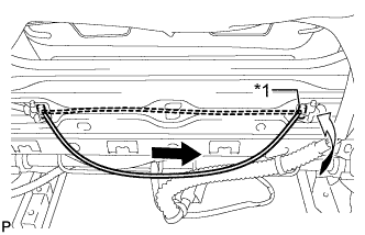
Text in Illustration *1 Cable End 
Pull Pull the cable and connect the cable end to the active headrest lower unit.
-
Attach the 7 hooks to install the actuator shield.
-
Text in Illustration *1 Hook *2 Hog Ring *3 Hog Ring Pliers Attach the 3 hooks.
-
Using hog ring pliers, install the upper part of the separate type front seatback cover to the separate type front seatback pad with new hog rings.
Note
-
Be careful not to damage the cover.
-
When installing the hog rings, avoid wrinkling the cover.
-
-
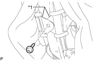
Text in Illustration *1 Seatback Cover Bracket Attach the seatback cover bracket with the screw.
Note
After the separate type front seatback cover is installed, make sure the seatback cover bracket is not twisted.
-
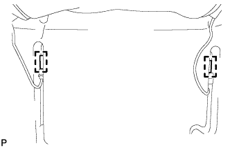
Pass the 2 straps through the 2 holes of the separate type front seatback pad to the backside.
-
Attach the 2 hooks to connect the 2 straps.
-
Attach the 2 hooks at the bottom of the separate type front seatback cover.
-
Attach the 2 hooks.
-
-
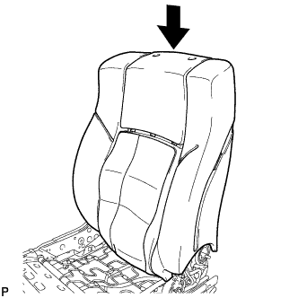
INSTALL SEPARATE TYPE FRONT SEATBACK ASSEMBLY LH
Tech Tips
Perform this procedure when it is necessary to remove and reinstall or replace the separate type front seatback assembly LH.
-
Using a T50 "TORX" socket wrench, install the separate type front seatback assembly LH to the front seat adjuster assembly LH with the 4 "TORX" bolts.
- Torque:
- 35 N*m { 357 kgf*cm, 26 ft.*lbf }
-
Attach the 4 wire harness clamps.
-
Attach the connector.
-
Install the front seat headrest assembly.
Note
Push in the front seat headrest assembly until the headrest lock engages.
-
Pass the cable through the hole of the seatback frame.
-
Attach the 2 claws to install the clip.
-
Text in Illustration *1 Cable End Pull the cable through the clip until the cable end reaches the clip.
-
Install a new cable tie.
-
Text in Illustration *1 Hook *2 Hog Ring *3 Hog Ring Pliers Attach the 2 hooks and close the seatback mat.
-
Using hog ring pliers, install a new hog ring.
-
Attach the 2 claws to connect the cable to the active headrest lower unit.
-
Attach the 2 claws to install the active headrest lower unit.
-
Text in Illustration *1 Cable End Pull Pull the cable and connect the cable end to the active headrest lower unit.
-
Attach the 7 hooks to install the actuator shield.
-
Text in Illustration *1 Hook *2 Hog Ring *3 Hog Ring Pliers Attach the 3 hooks.
-
Using hog ring pliers, install the upper part of the separate type front seatback cover to the separate type front seatback pad with new hog rings.
Note
-
Be careful not to damage the cover.
-
When installing the hog rings, avoid wrinkling the cover.
-
-
Text in Illustration *1 Seatback Cover Bracket Attach the seatback cover bracket with the screw.
Note
After the separate type front seatback cover is installed, make sure the seatback cover bracket is not twisted.
-
for Driver Side:
Connect the 2 connectors and attach the wire harness clamp.
-
for Front Passenger Side:
Connect the connector and attach the wire harness clamp.
-
Attach the wire harness clamp.
-
Pass the 2 straps through the 2 holes of the separate type front seatback pad to the backside.
-
Attach the 2 hooks to connect the 2 straps.
-
Attach the 2 hooks at the bottom of the separate type front seatback cover.
-
Attach the 2 hooks.
-
-
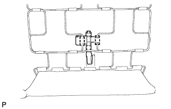
INSTALL POWER SEAT MOTOR ASSEMBLY (for Rear Lifter)
-
Install a nose piece to an air riveter or hand riveter. Then insert the mandrel part of a new φ4 mm rivet into the nose piece.
-
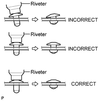
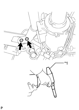
Text in Illustration *1 Air Riveter Using the air riveter or hand riveter, install the power seat motor assembly with a new rivet.
Tech Tips
If the rivet cannot be cut, pull it once and cut it.
Note
-

Do not pry the rivet with the riveter, as this will cause damage to the riveter and mandrel.
-

Confirm that the rivet is seated properly against the motor.
-
Do not tilt the riveter when installing the rivet to the power seat motor assembly.
-
Do not leave any space between the rivet head and power seat motor assembly.
-

Do not leave any space between the power seat motor assembly and front seat adjuster. Firmly hold together the 2 items while installing the rivet.
-
-
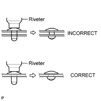
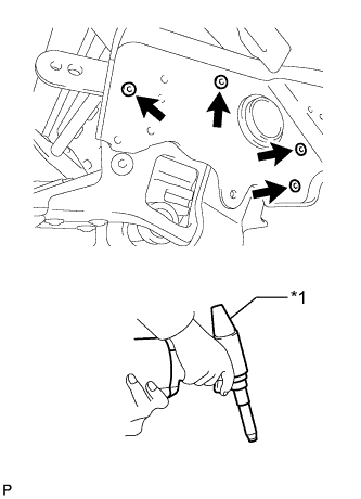
Text in Illustration *1 Air Riveter Using the air riveter or hand riveter, install 2 new rivets.
Tech Tips
If the rivet cannot be cut, pull it once and cut it.
Note
-
Do not pry the rivet with the riveter, as this will cause damage to the riveter and mandrel.
-
Confirm that the rivets are seated properly against the front seat adjuster.
-
Do not tilt the riveter when installing the rivet to the front seat adjuster.
-
Do not leave any space between the rivet head and front seat adjuster.
-
Do not leave any space between the front seat adjuster and power seat motor assembly. Firmly hold together the 2 items while installing the rivet.
-
-
-
INSTALL POWER SEAT MOTOR ASSEMBLY (for Front Vertical)
-
Install a nose piece to an air riveter or hand riveter. Then insert the mandrel part of a new φ4 mm rivet into the nose piece.
-
Text in Illustration *1 Air Riveter Using the air riveter or hand riveter, install the power seat motor assembly with 2 new rivets.
Tech Tips
If the rivet cannot be cut, pull it once and cut it.
Note
-
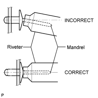
Do not pry the rivet with the riveter, as this will cause damage to the riveter and mandrel.
-
Confirm that the rivets are seated properly against the bracket.
-
Do not tilt the riveter when installing the rivet to the bracket.
-
Do not leave any space between the rivet head and bracket.
-
Do not leave any space between the power seat motor assembly and bracket. Firmly hold together the 2 items while installing the rivet.
-
-
Text in Illustration *1 Air Riveter Using the air riveter or hand riveter, install the power seat motor assembly with bracket with 2 new rivets.
Tech Tips
If the rivet cannot be cut, pull it once and cut it.
Note
-
Do not pry the rivet with the riveter, as this will cause damage to the riveter and mandrel.
-
Confirm that the rivets are seated properly against the bracket.
-
Do not tilt the riveter when installing the rivet to the power seat motor assembly with bracket.
-
Do not leave any space between the rivet head and power seat motor assembly with bracket.
-
Do not leave any space between the power seat motor assembly with bracket and front seat adjuster. Firmly hold together the 2 items while installing the rivet.
-
-
Text in Illustration *1 Air Riveter Using the air riveter or hand riveter, install 4 new rivets.
Tech Tips
If the rivet cannot be cut, pull it once and cut it.
Note
-
Do not pry the rivet with the riveter, as this will cause damage to the riveter and mandrel.
-
Confirm that the rivets are seated properly against the front seat adjuster.
-
Do not tilt the riveter when installing the rivet to the front seat adjuster.
-
Do not leave any space between the rivet head and front seat adjuster.
-
Do not leave any space between the motor with bracket and front seat adjuster. Firmly hold together the 2 items while installing the rivet.
-
-
Using a 6 mm socket hexagon wrench, install the bolt.
- Torque:
- 25 N*m { 255 kgf*cm, 18 ft.*lbf }
-
Install the shield bracket with the 3 screws.
-
Connect the connector.
-
-
INSTALL FRONT SEAT CUSHION HEATER ASSEMBLY LH
Note
When replacing either the front seat cushion heater assembly or separate type front seat cushion pad due to a malfunction, be sure to replace both of them with new parts.
-
Remove the peeling paper from a new front seat cushion heater assembly LH.
-
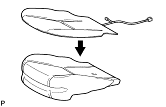
Install the front seat cushion heater assembly LH to a new separate type front seat cushion pad.
-
-
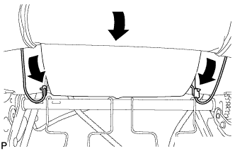
INSTALL SEPARATE TYPE FRONT SEAT CUSHION COVER
-
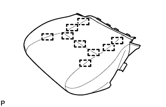
Attach the hooks to install the separate type front seat cushion cover to the separate type front seat cushion pad.
Note
-
Be careful not to damage the cover.
-
When attaching the hooks, avoid wrinkling the cover.
-
-
-
INSTALL SEAT CUSHION COVER WITH PAD
-
Attach the hooks to install the seat cushion cover with pad.
-
Connect the 2 connectors.
-
for Driver Side:
Attach the wire harness clamp.
-
for Front Passenger Side:
Attach the 2 hooks to connect the connector holder.
-
Install a new cable tie.
-
Connect the connector.
-
-
INSTALL FRONT SEAT INNER BELT ASSEMBLY LH
Tech Tips
-
Use the same procedure for the RH and LH sides.
-
The procedure listed below is for the LH side.
-
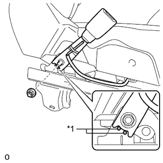
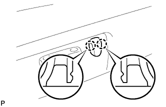
Text in Illustration *1 Protruding Part Install the front seat inner belt with the nut.
- Torque:
- 41 N*m { 418 kgf*cm, 30 ft.*lbf }
Note
Do not allow the anchor part of the front seat inner belt assembly to overlap the protruding part of the front seat adjuster.
-
for Driver Side:
Connect the connector and attach the clamps.
-
for Passenger Side:
Connect the connectors and attach the clamps.
-
-
INSTALL FRONT SEAT INNER CUSHION SHIELD LH
-
Text in Illustration *1 Hook *2 Wire Harness Clamp Attach the wire harness clamp and hook to install the front seat inner cushion shield LH.
-
Install the 2 screws.
-
-
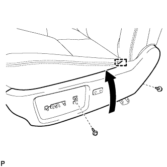
INSTALL FRONT POWER SEAT SWITCH
-
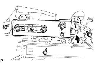
Install the front power seat switch with the 3 screws.
-
Connect the connector.
-
-
INSTALL LUMBAR FRONT POWER SEAT SWITCH (for Driver Side)
-
Install the lumbar front power seat switch with the 2 screws.
-
-
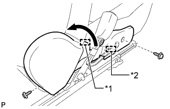
INSTALL FRONT SEAT NO. 1 INNER CUSHION SHIELD LH
-
Attach the 2 claws to install the front seat No. 1 inner cushion shield to the front seat cushion shield LH.
-
-
INSTALL FRONT SEAT CUSHION SHIELD LH WITH FRONT SEAT NO. 1 INNER CUSHION SHIELD LH
-
for Driver Side:
Connect the connector.
-
Attach the hook to install the front seat cushion shield LH with front seat inner No. 1 cushion shield.
-
Install the 2 screws.
-
Attach the 2 claws and install the 2 screws.
-
Attach the 2 rubber bands.
-
-
INSTALL SLIDE AND VERTICAL POWER SEAT SWITCH KNOB
-
Attach the 4 claws to install the slide and vertical power seat switch knob.
-
-
INSTALL RECLINING POWER SEAT SWITCH KNOB
-
Attach the 2 claws to install the reclining power seat switch knob.
-