PRE-CRASH SAFETY SYSTEM, Diagnostic DTC:B2074

| DTC Code | DTC Name |
|---|---|
| B2074 | Driver Side Seat Belt Buckle Switch Circuit Malfunction |
DESCRIPTION
This DTC is stored when there is a malfunction in the front seat inner belt buckle switch circuit for the driver side. The seat belt control ECU receives buckle switch condition information from the front seat inner belt and controls the pre-crash safety system.
| DTC Code | DTC Detection Condition | Trouble Area |
|---|---|---|
| B2074 | A malfunction in the front seat inner belt (buckle switch) circuit. |
|
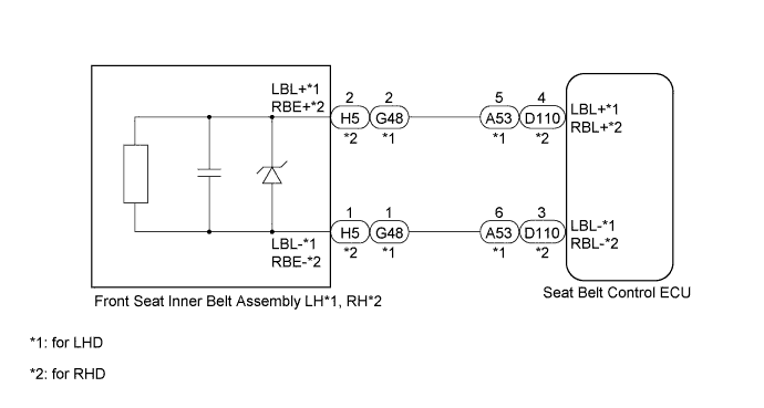
WIRING DIAGRAM
INSPECTION PROCEDURE
PROCEDURE
-
CHECK SEAT BELT CONTROL ECU
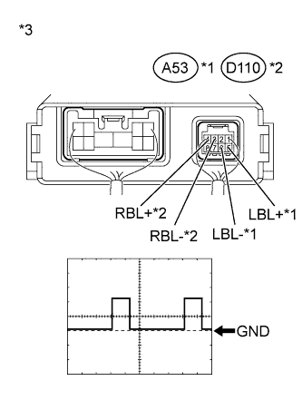
Text in Illustration *1 for LHD *2 for RHD *3 Component with harness connected
(Seat Belt Control ECU)
-
for LHD:
Remove the seat belt control ECU, but do not disconnect the connector Click here.
-
for RHD:
Remove the seat belt control ECU, but do not disconnect the connector Click here.
-
Using an oscilloscope, check the waveform.
Measurement Condition Item Content Tester Connection
-
A53-5 (LBL+) - A53-6 (LBL-)*1
-
D110-4 (RBL+) - D110-3 (RBL-)*2
Tool Setting 2 V/DIV., 20 ms/DIV. Condition Ignition switch ON, front seat belt fastened *1: for LHD
*2: for RHD
Result Result Proceed to NG A OK (for LHD) B OK (for RHD) C -
B 
REPLACE SEAT BELT CONTROL ECU Click here
C
REPLACE SEAT BELT CONTROL ECU Click here
A 
-
-
CHECK HARNESS AND CONNECTOR (SEAT BELT CONTROL ECU - FRONT SEAT INNER BELT)
*1: for LHD
*2: for RHD
-
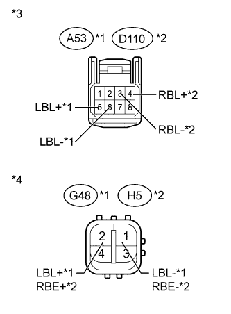
Text in Illustration *1 for LHD *2 for RHD *3 Front view of wire harness connector
(to Seat Belt Control ECU)
*4 Front view of wire harness connector
(to Front Seat Inner Belt)
Disconnect the A53*1 or D110*2 ECU connector.
-
Disconnect the G48*1 or H5*2 belt connector.
-
Measure the resistance according to the value(s) in the table below.
Standard Resistance for LHD Tester Connection Condition Specified Condition A53-6 (LBL-) - G48-1 (LBL-) Always Below 1 Ω A53-5 (LBL+) - G48-2 (LBL+) A53-6 (LBL-) - Body ground Always 10 kΩ or higher A53-5 (LBL+) - Body ground for RHD Tester Connection Condition Specified Condition D110-3 (RBL-) - H5-1 (RBE-) Always Below 1 Ω D110-4 (RBL+) - H5-2 (RBE+) D110-3 (RBL-) - Body ground Always 10 kΩ or higher D110-4 (RBL+) - Body ground Result Result Proceed to OK (for LHD) A OK (for RHD) B NG C
B
REPLACE FRONT SEAT INNER BELT ASSEMBLY RH Click here
C
REPAIR OR REPLACE HARNESS OR CONNECTOR
A 
REPLACE FRONT SEAT INNER BELT ASSEMBLY LH Click here
-