LIGHTING SYSTEM Door Courtesy Switch Circuit
DESCRIPTION
The main body ECU receives a door open/closed signal from each door courtesy light switch.
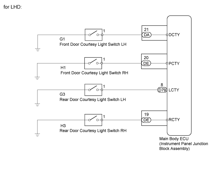
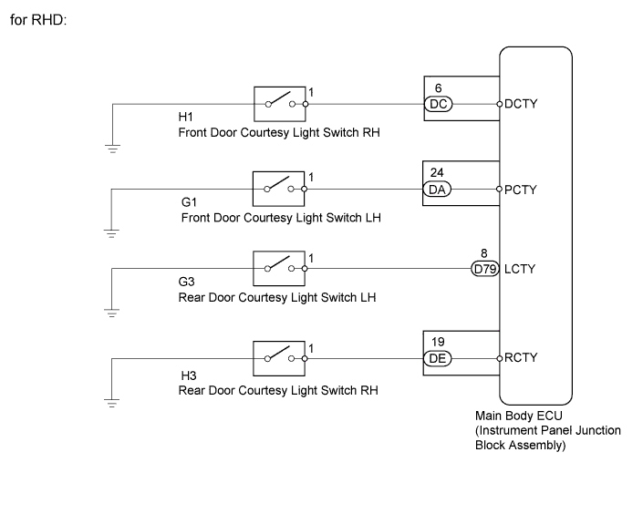
WIRING DIAGRAM
INSPECTION PROCEDURE
PROCEDURE
-
READ VALUE USING INTELLIGENT TESTER (DOOR COURTESY LIGHT SWITCH)
-
Connect the intelligent tester to the DLC3.
-
Turn the ignition switch to ON.
-
Turn the intelligent tester on.
-
Enter the following menus: Body / Main Body / Data List.
-
According to the display on the intelligent tester, read the Data List.
Main Body Tester Display Measurement Item/Range Normal Condition Diagnostic Note D Door Courtesy SW Driver side door courtesy light switch signal / ON or OFF ON: Driver side door courtesy light switch on
OFF: Driver side door courtesy light switch off
- P Door Courtesy SW Front passenger side door courtesy light switch signal / ON or OFF ON: Front passenger side door courtesy light switch on
OFF: Front passenger side door courtesy light switch off
- RL Door Courtesy SW Rear door courtesy light switch LH signal / ON or OFF ON: Rear door courtesy light switch LH on
OFF: Rear door courtesy light switch LH off
- RR Door Courtesy SW Rear door courtesy light switch RH signal / ON or OFF ON: Rear door courtesy light switch RH on
OFF: Rear door courtesy light switch RH off
- Result Result Proceed to OK A NG (Front door courtesy light switch LH does not operate) B NG (Front door courtesy light switch RH does not operate) C NG (Rear door courtesy light switch LH does not operate) D NG (Rear door courtesy light switch RH does not operate) E
B 
INSPECT FRONT DOOR COURTESY LIGHT SWITCH LH Click here
C
INSPECT FRONT DOOR COURTESY LIGHT SWITCH RH Click here
D
INSPECT REAR DOOR COURTESY LIGHT SWITCH LH Click here
E
INSPECT REAR DOOR COURTESY LIGHT SWITCH RH Click here
A 
PROCEED TO NEXT SUSPECTED AREA SHOWN IN PROBLEM SYMPTOMS TABLE Click here
-
-
INSPECT FRONT DOOR COURTESY LIGHT SWITCH LH

-
Remove the front door courtesy light switch LH Click here.
-
Measure the resistance according to the value(s) in the table below.
Standard Resistance Tester Connection Switch Condition Specified Condition 1 - Switch body Not pushed Below 1 Ω Pushed 10 kΩ or higher
NG 
REPLACE FRONT DOOR COURTESY LIGHT SWITCH LH Click here
OK 
-
-
CHECK HARNESS AND CONNECTOR (FRONT DOOR COURTESY LIGHT SWITCH LH - MAIN BODY ECU)
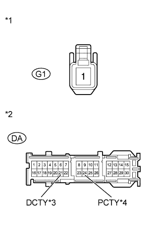
Text in Illustration *1 Front view of wire harness connector
(to Front Door Courtesy Light Switch LH)
*2 Front view of wire harness connector
(to Main Body ECU)
*3 for LHD *4 for RHD
-
Disconnect the G1 front door courtesy light switch LH connector.
-
Disconnect the DA main body ECU connector.
-
Measure the resistance according to the value(s) in the table below.
Standard Resistance for LHD Tester Connection Condition Specified Condition G1-1 - DA-21 (DCTY) Always Below 1 Ω G1-1 - Body ground Always 10 kΩ or higher for RHD Tester Connection Condition Specified Condition G1-1 - DA-24 (PCTY) Always Below 1 Ω G1-1 - Body ground Always 10 kΩ or higher
NG
REPAIR OR REPLACE HARNESS OR CONNECTOR
OK
REPLACE MAIN BODY ECU
-
-
INSPECT FRONT DOOR COURTESY LIGHT SWITCH RH
-
Remove the front door courtesy light switch RH Click here.
-
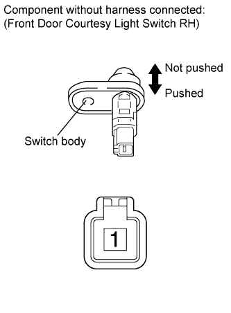
Measure the resistance according to the value(s) in the table below.
Standard Resistance Tester Connection Switch Condition Specified Condition 1 - Switch body Not pushed Below 1 Ω Pushed 10 kΩ or higher
NG
REPLACE FRONT DOOR COURTESY LIGHT SWITCH RH Click here
OK
-
-
CHECK HARNESS AND CONNECTOR (FRONT DOOR COURTESY LIGHT SWITCH RH - MAIN BODY ECU)
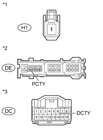
Text in Illustration *1 Front view of wire harness connector
(to Front Door Courtesy Light Switch RH)
*2 Front view of wire harness connector
(to Main Body ECU [for LHD])
*3 Front view of wire harness connector
(to Main Body ECU [for RHD])
-
Disconnect the H1 front door courtesy light switch RH connector.
-
Disconnect the DE or DC main body ECU connector.
-
Measure the resistance according to the value(s) in the table below.
Standard Resistance for LHD Tester Connection Condition Specified Condition H1-1 - DE-20 (PCTY) Always Below 1 Ω H1-1 - Body ground Always 10 kΩ or higher for RHD Tester Connection Condition Specified Condition H1-1 - DC-6 (DCTY) Always Below 1 Ω H1-1 - Body ground Always 10 kΩ or higher
NG
REPAIR OR REPLACE HARNESS OR CONNECTOR
OK
REPLACE MAIN BODY ECU
-
-
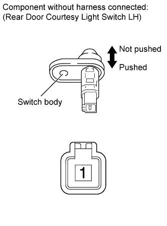
INSPECT REAR DOOR COURTESY LIGHT SWITCH LH
-
Remove the rear door courtesy light switch LH Click here.
-
Measure the resistance according to the value(s) in the table below.
Standard Resistance Tester Connection Switch Condition Specified Condition 1 - Switch body Not pushed Below 1 Ω Pushed 10 kΩ or higher
NG
REPLACE REAR DOOR COURTESY LIGHT SWITCH LH Click here
OK
-
-
CHECK HARNESS AND CONNECTOR (REAR DOOR COURTESY LIGHT SWITCH LH - MAIN BODY ECU)
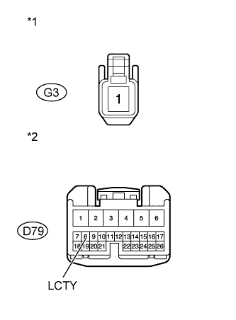
Text in Illustration *1 Front view of wire harness connector
(to Rear Door Courtesy Light Switch LH)
*2 Front view of wire harness connector
(to Main Body ECU)
-
Disconnect the G3 rear door courtesy light switch LH connector.
-
Disconnect the D79 main body ECU connector.
-
Measure the resistance according to the value(s) in the table below.
Standard Resistance Tester Connection Condition Specified Condition G3-1 - D79-8 (LCTY) Always Below 1 Ω G3-1 - Body ground Always 10 kΩ or higher
NG
REPAIR OR REPLACE HARNESS OR CONNECTOR
OK
REPLACE MAIN BODY ECU
-
-
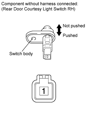
INSPECT REAR DOOR COURTESY LIGHT SWITCH RH
-
Remove the rear door courtesy light switch RH Click here.
-
Measure the resistance according to the value(s) in the table below.
Standard Resistance Tester Connection Switch Condition Specified Condition 1 - Switch body Not pushed Below 1 Ω Pushed 10 kΩ or higher
NG
REPLACE REAR DOOR COURTESY LIGHT SWITCH RH Click here
OK
-
-
CHECK HARNESS AND CONNECTOR (REAR DOOR COURTESY LIGHT SWITCH RH - MAIN BODY ECU)
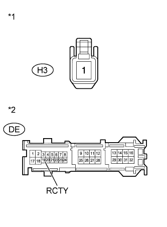
Text in Illustration *1 Front view of wire harness connector
(to Rear Door Courtesy Light Switch RH)
*2 Front view of wire harness connector
(to Main Body ECU)
-
Disconnect the H3 rear door courtesy light switch RH connector.
-
Disconnect the DE main body ECU connector.
-
Measure the resistance according to the value(s) in the table below.
Standard Resistance Tester Connection Condition Specified Condition H3-1 - DE-19 (RCTY) Always Below 1 Ω H3-1 - Body ground Always 10 kΩ or higher
NG
REPAIR OR REPLACE HARNESS OR CONNECTOR
OK
REPLACE MAIN BODY ECU
-