ENTRY AND START SYSTEM (for Start Function) Engine does not Start
DESCRIPTION
The push-button start function uses a push-type engine switch, which the driver can operate by merely carrying the key. This system consists primarily of the power management control ECU, engine switch, ID code box, steering lock ECU, key, ACC relay, IG1 relay, IG2 relay and certification ECU. The power management control ECU controls the system. This function operates in cooperation with the entry and start system.
WIRING DIAGRAM
-
Refer to Starter Signal Circuit:
-
for 1AD-FTV (for CCo): Click here.
-
for 1AD-FTV (for DPF): Click here.
-
for 2AD-FTV: Click here.
-
for 2AD-FHV: Click here.
INSPECTION PROCEDURE
Note
-
When using the intelligent tester with the engine switch off to troubleshoot: Connect the intelligent tester to the vehicle, and turn a courtesy light switch on and off at 1.5 second intervals until communication between the intelligent tester and vehicle begins.
-
Before performing the inspection, check that there are no problems related to the CAN communication system and LIN communication system.
-
Inspect the fuses for circuits related to this system before performing the following inspection procedure.
Tech Tips
After the certification ECU, steering lock actuator assembly (steering lock ECU), ID code box and/or ECM are/is replaced, perform the registration procedures described in the Service Bulletin.
-
EMERGENCY ENGINE START CONTROL
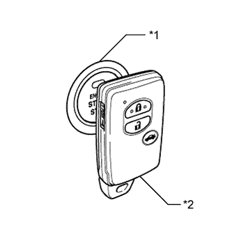
Text in Illustration *1 Engine Switch *2 Key
-
To operate the push-button start function when the key battery is low, hold the key against to the engine switch with the brake pedal*1 or clutch pedal*2 depressed.
-
*1: except Manual Transaxle
-
*2: for Manual Transaxle
-
-
PROCEDURE
-
CHECK IF ENGINE START (INITIALIZE STEERING LOCK)
-
Place the key on the seat. Move the shift lever to P*1 and depress the brake pedal*1 or clutch pedal*2.
-
*1: except Manual Transaxle
-
*2: for Manual Transaxle
-
-
Check that the engine switch indicator is illuminated in green, push the engine switch, and check that the engine starts.
-
Open and close the driver side door with the engine switch off.
-
Check if the engine can be started.
OK Engine can be started. Tech Tips
After the battery is discharged and then recharged, the engine may not start unless the steering lock is initialized using the above procedure.
NG 
READ VALUE USING INTELLIGENT TESTER AND CHECK FOR DTC Click here
OK 
USE SIMULATION METHOD TO CHECK Click here
-
-
READ VALUE USING INTELLIGENT TESTER AND CHECK FOR DTC
-
Read value using the intelligent tester (Power Supply Open).
-
Connect the intelligent tester to the DLC3.
-
Turn the engine switch on (IG).
-
Turn the intelligent tester on.
-
Enter the following menus: Body / Entry&Start / Data List.
-
According to the display on the intelligent tester, read the Data List.
Entry&Start Tester Display Measurement Item/Range Normal Condition Diagnostic Note Power Supply Open Power supply open / OK or NG (Past) OK: Power supply normal
NG (Past): Power supply open occurred in past
-
-
-
Check for DTCs
-
Enter the following menus: All / DTC.
-
Read the DTCs.
Result Result Proceed to No DTC is output, power supply open has not occurred in past A DTCs other than B2782 are output B Power supply open has occurred in past and/or DTC B2782 is output C
-
B 
GO TO DTC CHART Click here
C
GO TO STEERING LOCK SYSTEM (B2782) Click here
A 
-
-
CHECK ENGINE SWITCH CONDITION
-
Check if the power source mode changes.
-
When the key is inside the vehicle and the shift lever is in P*, push the engine switch and check that the power source mode changes.
*: except Manual Transaxle
Result Result Proceed to OK: off → on (ACC) → on (IG) → off A Power source mode does not change to on (IG) or on (ACC). B Power source mode does not change to on (IG). C Power source mode does not change to on (ACC). D
-
B
GO TO POWER SOURCE MODE DOES NOT CHANGE TO ON (IG AND ACC) Click here
C
GO TO POWER SOURCE MODE DOES NOT CHANGE TO ON (IG) Click here
D
GO TO POWER SOURCE MODE DOES NOT CHANGE TO ON (ACC) Click here
A
-
-
CHECK CRANKING FUNCTION
-
Check the engine cranking function.
-
except Manual Transaxle: When there is fuel in the fuel tank, the key is inside the vehicle, and the shift lever is in P, check that depressing the brake pedal and pressing the engine switch cranks the engine.
-
for Manual Transaxle: When there is fuel in the fuel tank and the key is inside the vehicle, check that depressing the clutch pedal and pressing the engine switch cranks the engine.
OK Engine cranks. Result Result Proceed to NG A OK for 1AD-FTV (for CCo) B OK for 1AD-FTV (for DPF) C OK for 2AD-FTV D OK for 2AD-FHV E
-
B
GO TO ECD SYSTEM (HOW TO PROCEED WITH TROUBLESHOOTING) Click here
C
GO TO ECD SYSTEM (HOW TO PROCEED WITH TROUBLESHOOTING) Click here
D
GO TO ECD SYSTEM (HOW TO PROCEED WITH TROUBLESHOOTING) Click here
E
GO TO ECD SYSTEM (HOW TO PROCEED WITH TROUBLESHOOTING) Click here
A
-
-
INSPECT PARK/NEUTRAL POSITION SWITCH OR CLUTCH START SWITCH
-
except Manual Transaxle:
-
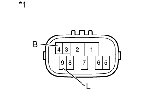
Text in Illustration *1 Component with harness connected
(Park/Neutral Position Switch)
Disconnect the B14 park/neutral position switch connector.
-
Measure the resistance according to the value(s) in the table below.
Standard Resistance Tester Connection Condition Specified Condition 4 (B) - 9(L) Shift lever in P or N Below 1 Ω Shift lever not in P or N 10 kΩ or higher
-
-
for Manual Transaxle:
-
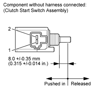
Disconnect the A3 clutch start switch connector.
-
Measure the resistance according to the value(s) in the table below.
Standard Resistance Tester Connection Condition Specified Condition 1 - 2 Pushed in
(Clutch pedal depressed)
Below 1 Ω Released
(Clutch pedal released)
10 kΩ or higher
-
NG
REPAIR OR REPLACE HARNESS OR CONNECTOR, OR REPLACE ST RELAY, PARK/NEUTRAL POSITION SWITCH OR CLUTCH START SWITCH Click here
OK
-
-
INSPECT STARTER RELAY (ST RELAY)
-
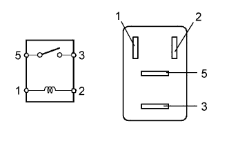
Remove the ST relay from the No. 1 relay block.
-
Measure the resistance according value(s) in the table below.
Standard Resistance Tester Connection Condition Specified Condition 3 - 5 When battery voltage is not applied to terminals 1 and 2 10 kΩ or higher When battery voltage is applied to terminals 1 and 2 Below 1 Ω
NG
REPAIR OR REPLACE HARNESS OR CONNECTOR, OR REPLACE ST RELAY, PARK/NEUTRAL POSITION SWITCH OR CLUTCH START SWITCH Click here
OK
-
-
CHECK HARNESS AND CONNECTOR (POWER MANAGEMENT CONTROL ECU - BODY GROUND)
-
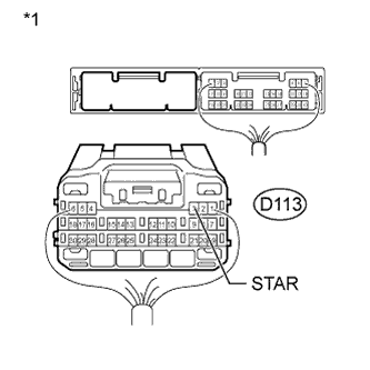
Text in Illustration *1 Rear view of wire harness connector
(to Power Management Control ECU)
Disconnect the D113 ECU connector.
-
Measure the resistance according to the value(s) in the table below.
Standard Resistance Tester Connection Condition Specified Condition D113-3 (STAR) - Body ground 20°C (68°F) 93.8 to 136.4 Ω
NG
OK
-
-
READ VALUE USING INTELLIGENT TESTER (STOP LIGHT SWITCH OR CLUTCH START SWITCH)
-
except Manual Transaxle:
-
Connect the intelligent tester to the DLC3.
-
Turn the engine switch on (IG).
-
Turn the intelligent tester on.
-
Enter the following menus: Body / Power Source Control / Data List.
-
According to the display on the intelligent tester, read the Data List.
Power Source Control Tester Display Measurement Item/Range Normal Condition Diagnostic Note Stop Light Switch1 Stop light switch 1 / ON or OFF ON: Brake pedal depressed
OFF: Brake pedal released
- OK ON (brake pedal depressed) or OFF (brake pedal released) appears on the screen according to the condition of the brake pedal.
-
-
for Manual Transaxle:
-
Connect the intelligent tester to the DLC3.
-
Turn the engine switch on (IG).
-
Turn the intelligent tester on.
-
Enter the following menus: Body / Power Source Control / Data List.
-
According to the display on the intelligent tester, read the Data List.
Power Source Control Tester Display Measurement Item/Range Normal Condition Diagnostic Note Neutral SW/Clutch SW Status of the clutch start switch/ ON or OFF ON: Clutch pedal depressed
OFF: Clutch pedal released
- OK ON (clutch pedal depressed) or OFF (clutch pedal released) appears on the screen according to the condition of the clutch pedal. Result Result Proceed to OK A NG (except Manual Transaxle) B NG (for Manual Transaxle) C
-
B
C
REPLACE POWER MANAGEMENT CONTROL ECU Click here
A
-
-
READ VALUE USING INTELLIGENT TESTER (STEERING UNLOCK SWITCH)
-
Connect the intelligent tester to the DLC3.
-
Turn the engine switch on (IG).
-
Turn the intelligent tester on.
-
Enter the following menus: Body / Power Source Control / Data List.
-
According to the display on the intelligent tester, read the Data List.
Power Source Control Tester Display Measurement Item/Range Normal Condition Diagnostic Note Steering Unlock Switch Steering unlock switch / ON or OFF ON: Steering lock released
OFF: Steering lock locked
- OK ON (steering lock released) or OFF (steering lock locked) appears on the screen according to the steering lock condition.
NG
OK
-
-
CHECK STEERING LOCK
-
Turn the engine switch from off to on (ACC) and check that the steering lock moves to the released position when the engine switch is on (ACC).
OK Lock moves to released position.
NG
GO TO STEERING LOCK SYSTEM (HOW TO PROCEED WITH TROUBLESHOOTING) Click here
OK
-
-
READ VALUE USING INTELLIGENT TESTER (ENGINE START REQUEST)
-
Connect the intelligent tester to the DLC3.
-
Turn the intelligent tester on.
Tech Tips
When using the intelligent tester with the engine switch off, turn on and off any of the door courtesy light switches repeatedly at 1.5 second intervals or less until communication between the tester and vehicle starts.
-
Enter the following menus: Body / Entry&Start / Data List.
-
According to the display on the intelligent tester, read the Data List.
-
Turn the engine switch on (IG).
Entry&Start Tester Display Measurement Item/Range Normal Condition Diagnostic Note Engine Start Request Start request signal response / OK or NG OK: Received
NG: Not received
The engine switch is pressed and held. OK OK appears on the screen.
NG
REPLACE CERTIFICATION ECU
OK
-
-
READ VALUE USING INTELLIGENT TESTER (L CODE)
-
Connect the intelligent tester to the DLC3.
-
Turn the intelligent tester on.
Tech Tips
When using the intelligent tester with the engine switch off, turn on and off any of the door courtesy light switches repeatedly at 1.5 second intervals or less until communication between the tester and vehicle starts.
-
Enter the following menus: Body / Entry&Start / Data List.
-
According to the display on the intelligent tester, read the Data List.
-
Turn the engine switch on (IG).
Entry&Start Tester Display Measurement Item/Range Normal Condition Diagnostic Note L Code Check L code certification result / OK or NG OK: L code certification result normal
NG: L code certification result abnormal
- OK OK (L code certification result normal) appears on the screen.
NG
GO TO ENGINE IMMOBILISER SYSTEM (HOW TO PROCEED WITH TROUBLESHOOTING) Click here
OK
-
-
READ VALUE USING INTELLIGENT TESTER (S CODE)
-
Connect the intelligent tester to the DLC3.
-
Turn the intelligent tester on.
Tech Tips
When using the intelligent tester with the engine switch off, turn on and off any of the door courtesy light switches repeatedly at 1.5 second intervals or less until communication between the tester and vehicle starts.
-
Enter the following menus: Body / Entry&Start / Data List.
-
According to the display on the intelligent tester, read the Data List.
-
Turn the engine switch on (IG).
Entry&Start Tester Display Measurement Item/Range Normal Condition Diagnostic Note S Code Check S code certification result / OK or NG OK: S code certification result normal
NG: S code certification result abnormal
- OK OK (S code certification result normal) appears on the screen.
NG
GO TO ENGINE IMMOBILISER SYSTEM
OK
-
-
READ VALUE USING INTELLIGENT TESTER (STARTER REQUEST SIGNAL)
-
Connect the intelligent tester to the DLC3.
-
Turn the intelligent tester on.
Tech Tips
When using the intelligent tester with the engine switch off, turn on and off any of the door courtesy light switches repeatedly at 1.5 second intervals or less until communication between the tester and vehicle starts.
-
Enter the following menus: Body / Power Source Control / Data List.
-
According to the display on the intelligent tester, read the Data List.
-
Turn the engine switch on (IG).
Power Source Control Tester Display Measurement Item/Range Normal Condition Diagnostic Note Starter Request Signal Starter request signal monitor / ON or OFF ON: ST relay on
OFF: ST relay off
except Manual Transaxle:
The engine switch is pressed and hold with the shift lever in P or N.
for Manual Transaxle:
The engine switch is pressed and held.
Note
Check that the engine switch indicator is illuminated in green and push the engine switch.
OK The Data List item changes from OFF to ON when the engine switch is pushed. Result Result Proceed to NG A OK for 1AD-FTV (for CCo) B OK for 1AD-FTV (for DPF) C OK for 2AD-FTV D OK for 2AD-FHV E
B
GO TO ECD SYSTEM (HOW TO PROCEED WITH TROUBLESHOOTING) Click here
C
GO TO ECD SYSTEM (HOW TO PROCEED WITH TROUBLESHOOTING) Click here
D
GO TO ECD SYSTEM (HOW TO PROCEED WITH TROUBLESHOOTING) Click here
E
GO TO ECD SYSTEM (HOW TO PROCEED WITH TROUBLESHOOTING) Click here
A
REPLACE POWER MANAGEMENT CONTROL ECU Click here
-
-
INSPECT STOP LIGHT SWITCH ASSEMBLY
-
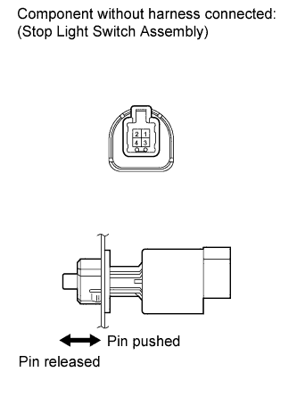
Remove the stop light switch assembly Click here.
-
Measure the resistance according to the value(s) in the table below.
Standard Resistance Tester Connection Switch Condition Specified Condition 1 - 2 Pin pushed 10 kΩ higher Pin released Below 1 Ω 3 - 4 Pin pushed Below 1 Ω Pin released 10 kΩ higher
NG
REPLACE STOP LIGHT SWITCH
OK
-
-
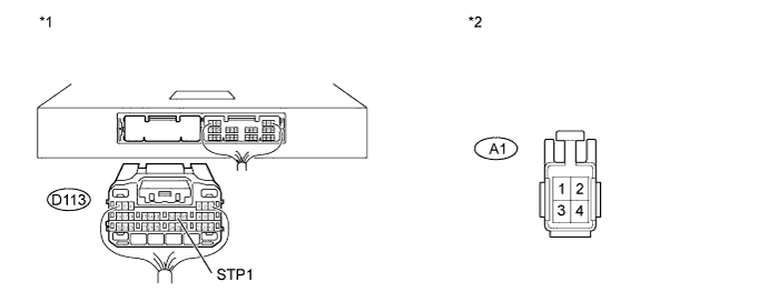
CHECK HARNESS AND CONNECTOR (POWER MANAGEMENT CONTROL ECU - STOP LIGHT SWITCH ASSEMBLY)
-
Disconnect the D113 power management control ECU connector.
-
Disconnect the A1 stop light switch assembly connector.
-
Measure the resistance according to the value(s) in the table below.
Standard Resistance Tester Connection Condition Specified Condition D113-11 (STP1) - A1-1 Always Below 1 Ω D113-11 (STP1) - Body ground Always 10 kΩ or higher -
Reconnect the A1 stop light switch assembly connector.
-
Measure the voltage according to the value(s) in the table below.
Standard Voltage Tester Connection Condition Specified Condition D113-11 (STP1) - Body ground Brake pedal not depressed Below 1.0 V Brake pedal depressed ((Voltage at terminal AM21 or AM22) minus 2.0 V) or higher Text in Illustration *1 Rear view of wire harness connector
(to Power Management Control ECU)
*2 Front view of wire harness connector
(to Stop Light Switch Assembly)
NG
REPAIR OR REPLACE HARNESS OR CONNECTOR
OK
REPLACE POWER MANAGEMENT CONTROL ECU Click here
-
-
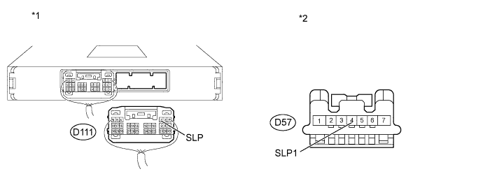
CHECK HARNESS AND CONNECTOR (POWER MANAGEMENT CONTROL ECU - STEERING LOCK ECU)
-
for Manual Tilt and Manual Telescopic Steering Column:
-
Disconnect the D111 power management control ECU connector.
-
Disconnect the D57 steering lock ECU connector.
-
Measure the resistance according to the value(s) in the table below.
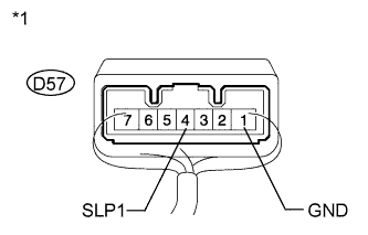
Standard Resistance Tester Connection Condition Specified Condition D57-4 (SLP1) - D111-3 (SLP) Always Below 1 Ω D57-4 (SLP1) or D111-3 (SLP) - Body ground Always 10 kΩ or higher Text in Illustration *1 Rear view of wire harness connector
(to Power Management Control ECU)
*2 Front view of wire harness connector
(to Steering Lock ECU)
-
-
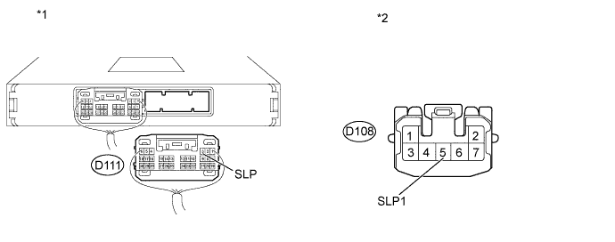
for Power Tilt and Power Telescopic Steering Column:
-
Disconnect the D111 power management control ECU connector.
-
Disconnect the D108 steering lock ECU connector.
-
Measure the resistance according to the value(s) in the table below.
Standard Resistance Tester Connection Condition Specified Condition D108-5 (SLP1) - D111-3 (SLP) Always Below 1 Ω D108-5 (SLP1) or D111-3 (SLP) - Body ground Always 10 kΩ or higher Text in Illustration *1 Rear view of wire harness connector
(to Power Management Control ECU)
*2 Front view of wire harness connector
(to Steering Lock ECU)
-
NG
REPAIR OR REPLACE HARNESS OR CONNECTOR
OK
-
-
INSPECT STEERING LOCK ACTUATOR ASSEMBLY (STEERING LOCK ECU)
-
for Manual Tilt and Manual Telescopic Steering Column:
-
Text in Illustration *1 Component with harness connected
(Steering Lock ECU)
Measure the resistance according to the value(s) in the table below.
Standard Resistance Tester Connection Condition Specified Condition D57-4 (SLP1) - Body ground Steering lock locked 10 kΩ or higher D57-4 (SLP1) - Body ground Steering lock released Below 1 Ω
-
-
for Power Tilt and Power Telescopic Steering Column:
-
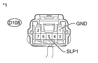
Text in Illustration *1 Component with harness connected
(Steering Lock ECU)
Measure the resistance according to the value(s) in the table below.
Standard Resistance Tester Connection Condition Specified Condition D108-5 (SLP1) - Body ground Steering lock locked 10 kΩ or higher D108-5 (SLP1) - Body ground Steering lock released Below 1 Ω Result Result Proceed to OK A NG (for Power Tilt and Power Telescopic Steering Column) B NG (for Manual Tilt and Manual Telescopic Steering Column) C
-
B
REPLACE STEERING LOCK ACTUATOR ASSEMBLY (STEERING LOCK ECU) Click here
C
REPLACE STEERING LOCK ACTUATOR ASSEMBLY (STEERING LOCK ECU) Click here
A
REPLACE POWER MANAGEMENT CONTROL ECU Click here
-
-
REPAIR OR REPLACE HARNESS OR CONNECTOR, OR REPLACE ST RELAY, PARK/NEUTRAL POSITION SWITCH OR CLUTCH START SWITCH
-
Replace the ST relay or clutch start switch with a new or normally functioning part, or repair or replace any damaged wire harness or connector.
NEXT
-
-
READ VALUE USING INTELLIGENT TESTER (STARTER REQUEST SIGNAL)
-
Connect the intelligent tester to the DLC3.
-
Turn the intelligent tester on.
Tech Tips
When using the intelligent tester with the engine switch off, turn on and off any of the door courtesy light switches repeatedly at 1.5 second intervals or less until communication between the tester and vehicle starts.
-
Enter the following menus: Body / Power Source Control / Data List.
-
According to the display on the intelligent tester, read the Data List.
-
Turn the engine switch on (IG).
Power Source Control Tester Display Measurement Item/Range Normal Condition Diagnostic Note Starter Request Signal Starter request signal monitor / ON or OFF ON: ST relay on.
OFF: ST relay off.
The engine switch is pressed and held. Note
Check that the engine switch indicator is illuminated in green and push the engine switch.
OK The Data List item changes from OFF to ON when the engine switch is pushed.
NG
REPLACE POWER MANAGEMENT CONTROL ECU Click here
OK
-
-
CHECK IF ENGINE STARTS
-
Place the key on the seat. Move the shift lever to P*1 and depress the brake pedal*1 or clutch pedal*2.
-
*1: except Manual Transaxle
-
*2: for Manual Transaxle
-
-
Check that the engine switch indicator is illuminated in green, push the engine switch, and check that the engine starts.
-
Open and close the driver side door with the engine switch off.
-
Check if the engine can be started.
OK Engine can be started. Tech Tips
After the battery is discharged and then recharged, the engine may not start unless the steering lock is initialized using the above procedure.
Result Result Proceed to OK A NG for 1AD-FTV (for CCo) B NG for 1AD-FTV (for DPF) C NG for 2AD-FTV D NG for 2AD-FHV E
B
GO TO ECD SYSTEM (Starter Signal Circuit) Click here
C
GO TO ECD SYSTEM (Starter Signal Circuit) Click here
D
GO TO ECD SYSTEM (Starter Signal Circuit) Click here
E
GO TO ECD SYSTEM (Starter Signal Circuit) Click here
A
END
-