ENTRY AND START SYSTEM (for Start Function), Diagnostic DTC:B2271

| DTC Code | DTC Name |
|---|---|
| B2271 | Ignition Hold Monitor Malfunction |
DESCRIPTION
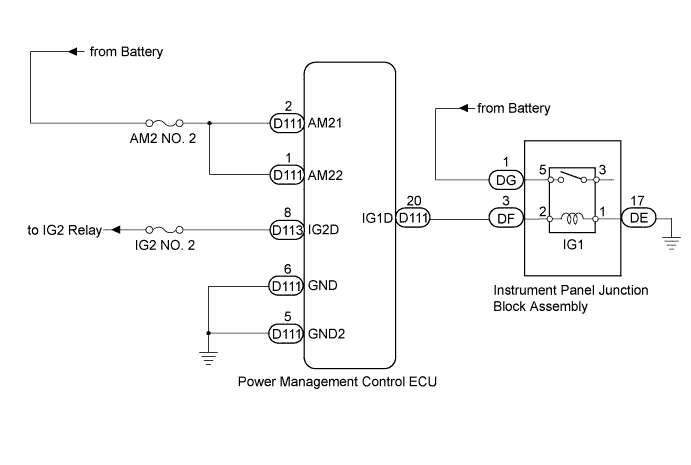
This DTC is stored when a problem, such as an open in the AM2 NO. 2 fuse, an open or short in the wire harness between the fuse and power management control ECU, a short in the IG output circuit inside the power management control ECU, a short between the power management control ECU and relay, or a short in the relay, is detected.
Tech Tips
When the power management control ECU is replaced with a new one and the cable is connected to the negative (-) battery terminal, the power source mode is reset to on (IG). When the battery is removed and reinstalled, the power source mode that was selected when the battery was removed is restored.
| DTC Code | DTC Detection Condition | Trouble Area |
|---|---|---|
| B2271 | The hold circuit, IG1 relay actuation circuit or IG2 relay actuation circuit inside power management control ECU is open or shorted. |
|
WIRING DIAGRAM
INSPECTION PROCEDURE
Note
-
When using the intelligent tester with the engine switch off to troubleshoot: Connect the intelligent tester to the vehicle, and turn a courtesy light switch on and off at 1.5 second intervals until communication between the intelligent tester and vehicle begins.
-
Before performing the inspection, check that there are no problems related to the CAN communication system and LIN communication system.
-
Inspect the fuses for circuits related to this system before performing the following inspection procedure.
PROCEDURE
-
CHECK HARNESS AND CONNECTOR (BATTERY - POWER MANAGEMENT CONTROL ECU)
-
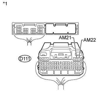
Text in Illustration *1 Rear view of wire harness connector
(to Power Management Control ECU)
Disconnect the D111 power management control ECU connector.
-
Measure the voltage according to the value(s) in the table below.
Standard Voltage Tester Connection Condition Specified Condition D111-2 (AM21) - Body ground Always 9.5 to 16 V D111-1 (AM22) - Body ground
NG 
REPAIR OR REPLACE HARNESS OR CONNECTOR
OK 
-
-
CHECK HARNESS AND CONNECTOR (POWER MANAGEMENT CONTROL ECU - BODY GROUND)
-
Disconnect the D111 power management control ECU connector.
-
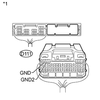
Text in Illustration *1 Rear view of wire harness connector
(to Power Management Control ECU)
Measure the resistance according to the value(s) in the table below.
Standard Resistance Tester Connection Condition Specified Condition D111-6 (GND) - Body ground Always Below 1 Ω D111-5 (GND2) - Body ground
NG
REPAIR OR REPLACE HARNESS OR CONNECTOR
OK
-
-
CHECK INSTRUMENT PANEL JUNCTION BLOCK ASSEMBLY (IG1 RELAY)
-
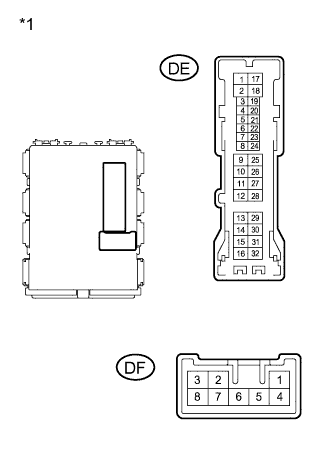
Text in Illustration *1 Component without harness connected
(Instrument Panel Junction Block Assembly)
Disconnect the DE and DF instrument panel junction block assembly connectors.
-
Measure the resistance according to the value(s) in the table below.
Standard Resistance Tester Connection Condition Specified Condition DF-3 - DE-17 (relay coil side circuit) 20°C (68°F) 151 to 203 Ω
NG 
REPAIR OR REPLACE HARNESS OR CONNECTOR, OR REPLACE INSTRUMENT PANEL JUNCTION BLOCK ASSEMBLY (IG1 RELAY) Click here
OK
-
-
INSPECT IG1 RELAY
-
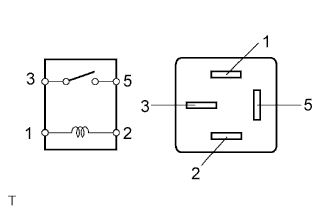
Remove the IG1 relay from the instrument panel junction block assembly.
-
Measure the resistance according to the value(s) in the table below.
Standard Resistance Tester Connection Condition Specified Condition 3 - 5 When battery voltage is not applied to terminals 1 and 2 10 kΩ or higher 3 - 5 When battery voltage is applied to terminals 1 and 2 Below 1 Ω
NG
REPAIR OR REPLACE HARNESS OR CONNECTOR, OR REPLACE INSTRUMENT PANEL JUNCTION BLOCK ASSEMBLY (IG1 RELAY) Click here
OK
-
-
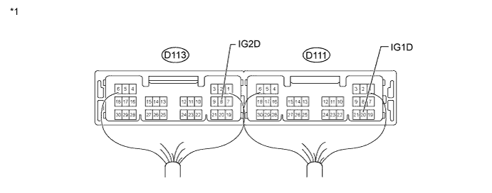
CHECK HARNESS AND CONNECTOR (POWER MANAGEMENT CONTROL ECU - BODY GROUND)
-
Disconnect the D111 and D113 power management control ECU connectors.
-
Measure the resistance according to the value(s) in the table below.
Standard Resistance Tester Connection Condition Specified Condition D113-8 (IG2D) - Body ground 20°C (68°F) 255 to 387 Ω D111-20 (IG1D) - Body ground 20°C (68°F) 151 to 203 Ω Text in Illustration *1 Rear view of wire harness connector
(to Power Management Control ECU)
NG
REPAIR OR REPLACE HARNESS OR CONNECTOR, OR REPLACE INSTRUMENT PANEL JUNCTION BLOCK ASSEMBLY (IG1 RELAY) Click here
OK
-
-
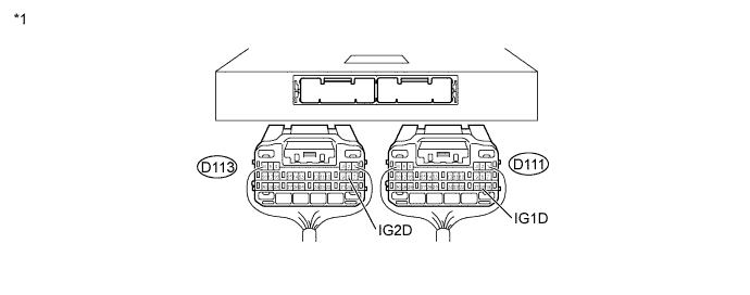
CHECK POWER MANAGEMENT CONTROL ECU
-
Connect the power management control ECU connectors.
-
Measure the voltage according to the value(s) in the table below.
Standard Voltage Tester Connection Switch Condition Specified Condition D113-8 (IG2D) - Body ground Engine switch off Below 1.0 V Engine switch on (IG) ((Voltage at terminal AM21 or AM22) minus 2.0 V) or higher D111-20 (IG1D) - Body ground Engine switch off Below 1.0 V Engine switch on (IG) ((Voltage at terminal AM21 or AM22) minus 2.0 V) or higher Text in Illustration *1 Component with harness connected
(Power Management Control ECU)
NG
REPLACE POWER MANAGEMENT CONTROL ECU Click here
OK 
USE SIMULATION METHOD TO CHECK Click here
-
-
REPAIR OR REPLACE HARNESS OR CONNECTOR, OR REPLACE INSTRUMENT PANEL JUNCTION BLOCK ASSEMBLY (IG1 RELAY)
-
Replace the instrument panel junction block (IG1 relay) with a new or normally functioning part, or repair or replace any damaged wire harness or connector.
NEXT
-
-
CHECK POWER MANAGEMENT CONTROL ECU
-
Connect the power management control ECU connectors.
-
Measure the voltage according to the value(s) in the table below.
Standard Voltage Tester Connection Switch Condition Specified Condition D113-8 (IG2D) - Body ground Engine switch off Below 1.0 V Engine switch on (IG) ((Voltage at terminal AM21 or AM22) minus 2.0 V) or higher D111-20 (IG1D) - Body ground Engine switch off Below 1.0 V Engine switch on (IG) ((Voltage at terminal AM21 or AM22) minus 2.0 V) or higher Text in Illustration *1 Component with harness connected
(Power Management Control ECU)
NG
REPLACE POWER MANAGEMENT CONTROL ECU Click here
OK
END
-