ENTRY AND START SYSTEM (for Entry Function) Back Door Entry Lock Function does not Operate
DESCRIPTION
If the back door entry lock function does not operate but the back door open function operates, the communication line between the vehicle and electrical key transmitter is normal. The entry lock switch circuit (certification ECU → back door switch) may be faulty.
WIRING DIAGRAM
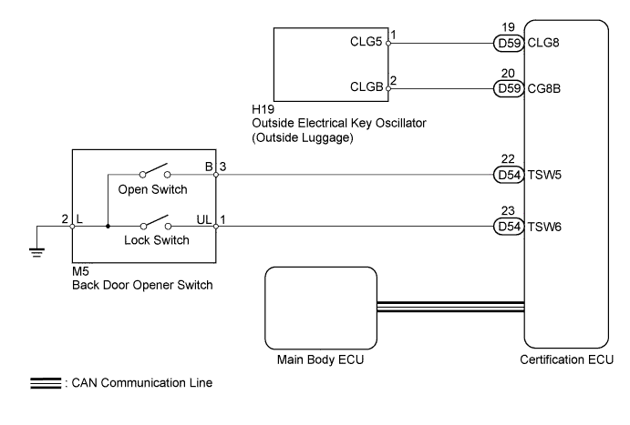
INSPECTION PROCEDURE
Note
-
The entry and start system (for entry function) uses a multiplex communication system (LIN communication system) and CAN communication system. Inspect the communication function by following How to Proceed with Troubleshooting Click here. Troubleshoot the entry and start system (for entry function) after confirming that the communication system is functioning properly.
-
When using the intelligent tester with the engine switch off to troubleshoot: Connect the intelligent tester to the DLC3, and turn a courtesy light switch on and off at 1.5-second intervals until communication between the tester and vehicle begins.
-
When checking the entry lock operation multiple times, the lock operation may be limited to 2 consecutive operations according to the settings. In order to perform the entry lock operation 3 or more times, an unlock operation must be performed once (any type of unlock operation is sufficient). However, only consecutive entry lock operations are limited. Using the wireless lock or other types of lock operations, it is possible to perform consecutive lock operations without this limitation.
PROCEDURE
-
CHECK POWER DOOR LOCK OPERATION
-
When the door control switch of the master switch assembly is operated, check that the locked doors unlock Click here.
OK Door locks operate normally.
NG 
GO TO POWER DOOR LOCK CONTROL SYSTEM Click here
OK 
-
-
READ VALUE USING INTELLIGENT TESTER (BACK DOOR LOCK SWITCH)
-
Using the intelligent tester, read the Data List.
Entry&Start Tester Display Measurement Item/Display Normal Condition Diagnostic Note Tr/B-Door Lock SW Back door lock switch / ON or OFF ON: Back door lock switch pushed
OFF: Back door lock switch not pushed
- OK "ON" (switch is pushed) or "OFF" (switch is not pushed) appears on the screen.
NG 
CHECK BACK DOOR OPENER SWITCH Click here
OK 
REPLACE CERTIFICATION ECU
-
-
CHECK BACK DOOR OPENER SWITCH
-
Remove the back door opener switch Click here.
-
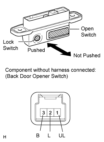
Measure the resistance according to the value(s) in the table below.
Standard Resistance Tester Connection Switch Condition Specified Condition 1 (UL) - 2 (L)
3 (B) - 2 (L)
No switch 10 kΩ or higher 1 (UL) - 2 (L) Lock switch pushed Below 1 Ω 3 (B) - 2 (L) Open switch pushed Below 1 Ω
NG
REPLACE BACK DOOR OPENER SWITCH Click here
OK
-
-
CHECK HARNESS AND CONNECTOR (CERTIFICATION ECU - BACK DOOR OPENER SWITCH)
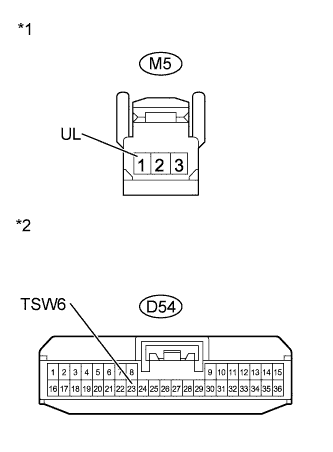
Text in Illustration *1 Front view of wire harness connector
(to Back Door Opener Switch)
*2 Front view of wire harness connector
(to Certification ECU)
-
Disconnect the M5 switch connector.
-
Disconnect the D54 ECU connector.
-
Measure the resistance according to the value(s) in the table below.
Standard Resistance Tester Connection Condition Specified Condition M5-1 (UL) - D54-23 (TSW6) Always Below 1 Ω M5-1 (UL) - Body ground Always 10 kΩ or higher
NG
REPAIR OR REPLACE HARNESS OR CONNECTOR
OK
REPLACE CERTIFICATION ECU
-