ENTRY AND START SYSTEM (for Start Function), Diagnostic DTC:B2281

| DTC Code | DTC Name |
|---|---|
| B2281 | "P" Signal Malfunction |
DESCRIPTION
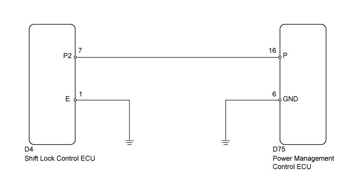
This DTC is stored when there is an abnormal circuit between the power management control ECU and the shift lock control ECU.
Tech Tips
When the power management control ECU is replaced with a new one and the cable is connected to the negative (-) battery terminal, the power source mode is reset to on (IG). When the battery is removed and reinstalled, the power source mode that was selected when the battery was removed is restored.
| DTC No. | DTC Detection Condition | Trouble Area |
|---|---|---|
| B2281 | Communication or the communication line between the power management control ECU and shift lock control ECU is abnormal. |
|
WIRING DIAGRAM
INSPECTION PROCEDURE
PROCEDURE
-
READ VALUE USING INTELLIGENT TESTER (SHIFT P SIGNAL)
-
Connect the intelligent tester to the DLC3.
-
Turn the engine switch on (IG).
-
Turn the intelligent tester on.
-
Enter the following menus: Body / Power Source Control / Data List.
-
According to the display on the intelligent tester, read the Data List.
Power Source Control Tester Display Measurement Item/Range Normal Condition Diagnostic Note Shift P Signal Shift P position signal/ON or OFF ON: Shift lever in P
OFF: Shift lever not in P
- OK ON (shift lever in P) or OFF (shift lever not in P) appears on the screen according to the shift lever position.
NG 
INSPECT SHIFT LOCK CONTROL ECU Click here
OK 
REPLACE POWER MANAGEMENT CONTROL ECU Click here
-
-
INSPECT SHIFT LOCK CONTROL ECU
-
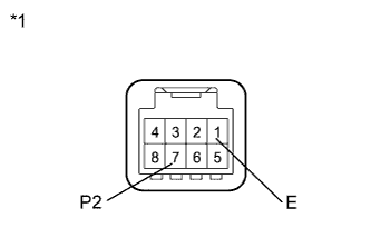
Text in Illustration *1 Component with harness connected
(Shift Lock Control ECU)
Measure the resistance according to the value(s) in the table below.
Standard Resistance Tester Connection Condition Specified Condition 7 (P2) - 1 (E) Shift lever in P Below 1 Ω 7 (P2) - 1 (E) Shift lever not in P 10 kΩ or higher
NG 
REPLACE SHIFT LOCK CONTROL ECU Click here
OK 
-
-
CHECK HARNESS AND CONNECTOR (POWER MANAGEMENT CONTROL ECU AND BODY GROUND - SHIFT LOCK CONTROL ECU)
-
Disconnect the D75 connector from the power management control ECU.
-
Disconnect the D4 connector from the shift lock control ECU.
-
Measure the resistance according to the value(s) in the table below.
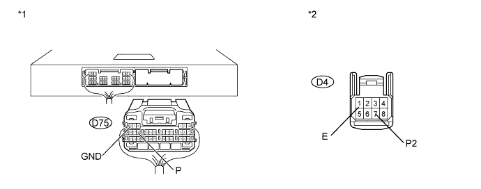
Standard Resistance Tester Connection Condition Specified Condition D75-16 (P) - D4-7 (P2) Always Below 1 Ω D75-16 (P) or D4-7 (P2) - Body ground Always 10 kΩ or higher D4-1 (E) - Body ground Always Below 1 Ω Text in Illustration *1 Rear view of wire harness connector
(to Power Management Control ECU)
*2 Front view of wire harness connector
(to Shift Lock Control ECU)
NG
REPAIR OR REPLACE HARNESS OR CONNECTOR
OK
REPLACE POWER MANAGEMENT CONTROL ECU Click here
-