ENTRY AND START SYSTEM (for Start Function), Diagnostic DTC:B2282, B2283

| DTC Code | DTC Name |
|---|---|
| B2282 | Vehicle Speed Signal Malfunction |
| B2283 | Vehicle Speed Sensor Malfunction |
DESCRIPTION
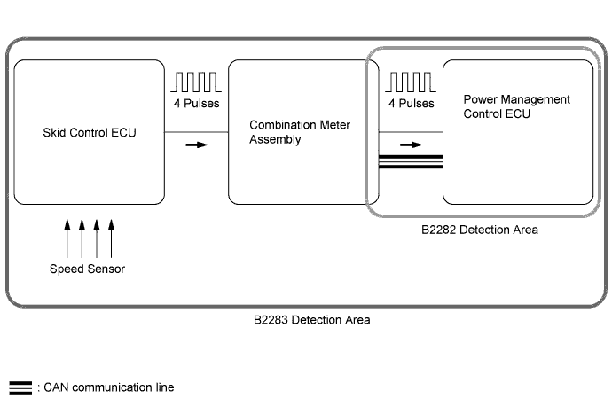
The power management control ECU and the combination meter are connected by a cable and the CAN communication lines. This DTC is stored when the cable information of the vehicle speed signal and CAN information of the vehicle speed signal are inconsistent.
Tech Tips
When the power management control ECU is replaced with a new one and the cable is connected to the negative (-) battery terminal, the power source mode is reset to on (IG). When the battery is removed and reinstalled, the power source mode that was selected when the battery was removed is restored.
| DTC Code | DTC Detection Condition | Trouble Area |
|---|---|---|
| B2282 | The cable information of the vehicle speed signal and CAN information of the vehicle speed signal are inconsistent. |
|
The skid control ECU converts signals from the speed sensor into 4-pulse signals and sends them to the combination meter. After these signals are converted into a more precise rectangular waveform by the waveform shaping circuit inside the combination meter, they are then transmitted to the power management control ECU. The power management control ECU determines the vehicle speed based on the frequencies of these pulse signals.
| DTC Code | DTC Detection Condition | Trouble Area |
|---|---|---|
| B2283 | Both conditions are met:
|
|
Tech Tips
-
A voltage of 12 V or 5 V is output from each ECU and then input to the combination meter. The signal is changed to a pulse signal at the transistor in the combination meter. Each ECU controls its respective system based on the pulse signal.
-
If a short occurs in an ECU, all systems related to the components in the diagram above will not operate normally.
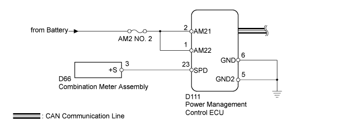
WIRING DIAGRAM
INSPECTION PROCEDURE
Note
-
When using the intelligent tester with the engine switch off to troubleshoot: Connect the intelligent tester to the vehicle, and turn a courtesy light switch on and off at 1.5 second intervals until communication between the intelligent tester and vehicle begins.
-
Before performing the inspection, check that there are no problems related to the CAN communication system and LIN communication system.
-
Inspect the fuses for circuits related to this system before performing the following inspection procedure.
PROCEDURE
-
CHECK HARNESS AND CONNECTOR (BATTERY - POWER MANAGEMENT CONTROL ECU)
-
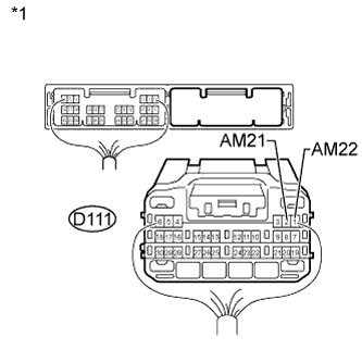
Text in Illustration *1 Rear view of wire harness connector
(to Power Management Control ECU)
Disconnect the D111 power management control ECU connector.
-
Measure the voltage according to the value(s) in the table below.
Standard Voltage Tester Connection Condition Specified Condition D111-2 (AM21) - Body ground Always 9.5 to 16 V D111-1 (AM22) - Body ground
NG 
REPAIR OR REPLACE HARNESS OR CONNECTOR
OK 
-
-
CHECK HARNESS AND CONNECTOR (POWER MANAGEMENT CONTROL ECU - BODY GROUND)
-
Disconnect the D111 power management control ECU connector.
-
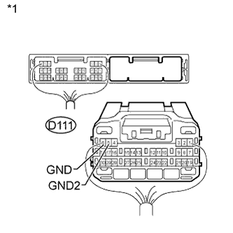
Text in Illustration *1 Rear view of wire harness connector
(to Power Management Control ECU)
Measure the resistance according to the value(s) in the table below.
Standard Resistance Tester Connection Condition Specified Condition D111-6 (GND) - Body ground Always Below 1 Ω D111-5 (GND2) - Body ground
NG
REPAIR OR REPLACE HARNESS OR CONNECTOR
OK
-
-
CHECK HARNESS AND CONNECTOR (POWER MANAGEMENT CONTROL ECU - COMBINATION METER)
-
Disconnect the D111 power management control ECU connector.
-
Disconnect the D66 combination meter assembly connector.
-
Measure the resistance according to the value(s) in the table below.
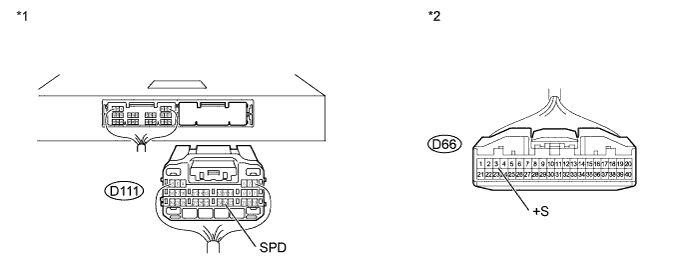
Standard Resistance Tester Connection Condition Specified Condition D111-23 (SPD) - D66-3 (+S) Always Below 1 Ω D111-23 (SPD) - Body ground Always 10 kΩ or higher Text in Illustration *1 Rear view of wire harness connector
(to Power Management Control ECU)
*2 Front view of wire harness connector
(to Combination Meter Assembly)
NG
REPAIR OR REPLACE HARNESS OR CONNECTOR
OK
-
-
READ VALUE USING INTELLIGENT TESTER (VEHICLE SPEED SIGNAL)
-
Connect the intelligent tester to the DLC3.
-
Turn the engine switch on (IG).
-
Turn the intelligent tester on.
-
Enter the following menus: Body / Power Source Control / Data List.
-
According to the display on the intelligent tester, read the Data List.
Power Source Control Tester Display Measurement Item/Range Normal Condition Diagnostic Note Vehicle Speed Signal Vehicle speed signal / Stop or Run Stop: Vehicle stopped
Run: Vehicle driven (5 km/h (3 mph) or higher)
- OK Stop (Vehicle stopped) or Run (Vehicle driven) appears on the screen according the vehicle speed.
NG 
CHECK POWER MANAGEMENT CONTROL ECU Click here
OK 
GO TO METER/GAUGE SYSTEM (HOW TO PROCEED WITH TROUBLESHOOTING) Click here
-
-
CHECK POWER MANAGEMENT CONTROL ECU
-
Using an oscilloscope, check the vehicle speed input signal waveform from the combination meter at the terminal of the power management control ECU.
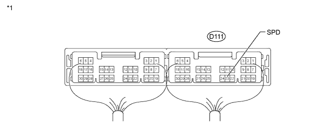
Text in Illustration *1 Component with harness connected
(Power Management Control ECU)
-
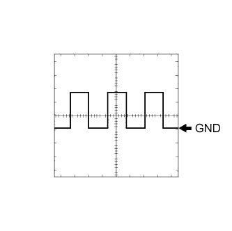
Check the signal waveform according to the condition(s) in the table below.
Standard Frequency Tester Connection Condition Vehicle condition Specified Condition D111-23 (SPD) - Body ground 5 V/DIV., 10 ms./DIV. Engine switch on (IG), vehicle being driven at approx. 20 km/h (12 mph) Correct waveform as shown in illustration
NG
GO TO METER/GAUGE SYSTEM (TERMINALS OF ECU) Click here
OK
REPLACE POWER MANAGEMENT CONTROL ECU Click here
-