POWER DOOR LOCK CONTROL SYSTEM All Doors LOCK/UNLOCK Functions do not Operate Via Master Switch, Driver Side Door Key Cylinder
DESCRIPTION
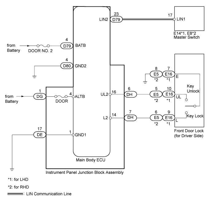
The main body ECU receives switch signals from the master switch, and driver side door key cylinder switch signals from the front door lock. The main body ECU (instrument panel junction block assembly) activates the door lock motor on each door according to these signals.
WIRING DIAGRAM
INSPECTION PROCEDURE
Note
Inspect the fuses and bulbs for circuits related to this system before performing the following inspection procedure.
PROCEDURE
-
CHECK DOOR LOCK OPERATION
-
Check the door lock operation.
Result Result Proceed to All doors cannot be locked with master switch and driver side door key cylinder A All doors cannot be locked with master switch B All doors cannot be locked with driver side door key cylinder C
B 
CHECK POWER WINDOW REGULATOR MASTER SWITCH ASSEMBLY (OPERATION) Click here
C
READ VALUE USING INTELLIGENT TESTER (DOOR KEY-LINKED LOCK AND UNLOCK SWITCH) Click here
A 
-
-
CHECK HARNESS AND CONNECTOR (MAIN BODY ECU - BATTERY AND BODY GROUND)
-
Disconnect the DE, DG, D79 and D80 ECU connectors.
-
Measure the voltage and resistance according to the value(s) in the table below.
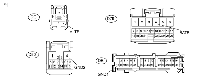
Standard Voltage Tester Connection Condition Specified Condition DG-1 (ALTB) - Body ground Always 11 to 14 V D79-4 (BATB) - Body ground Always 11 to 14 V Standard Resistance Tester Connection Condition Specified Condition DE-17 (GND1) - Body ground Always Below 1 Ω D80-4 (GND2) - Body ground Always Below 1 Ω Text in Illustration *1 Front view of wire harness connector
(to Main body ECU)
NG 
REPAIR OR REPLACE HARNESS OR CONNECTOR
OK 
REPLACE MAIN BODY ECU (INSTRUMENT PANEL JUNCTION BLOCK ASSEMBLY)
-
-
CHECK POWER WINDOW REGULATOR MASTER SWITCH ASSEMBLY (OPERATION)
-
Replace the master switch with a normally functioning one Click here.
-
Check that all doors can be locked and unlocked by using the master switch.
OK All doors can be locked and unlocked with master switch.
NG
REPLACE MAIN BODY ECU (INSTRUMENT PANEL JUNCTION BLOCK ASSEMBLY)
OK
END (POWER WINDOW REGULATOR MASTER SWITCH ASSEMBLY IS DEFECTIVE)
-
-
READ VALUE USING INTELLIGENT TESTER (DOOR KEY-LINKED LOCK AND UNLOCK SWITCH)
-
Use the Data List to check if the door key-linked lock and unlock switches are functioning properly.
Main Body ECU Tester Display Measurement Item/Range Normal Condition Diagnostic Note Door Key Linked Lock SW Door key-linked switch lock signal / ON or OFF ON: Driver side door key cylinder turned to lock position
OFF: Driver side door key cylinder not turned
- Door Key Linked Unlock SW Door key-linked switch unlock signal / ON or OFF ON: Driver side door key cylinder turned to unlock position
OFF: Driver side door key cylinder not turned
- OK On tester screen, each item changes between ON and OFF according to above chart.
NG
CHECK HARNESS AND CONNECTOR (FRONT DOOR LOCK - MAIN BODY ECU AND BODY GROUND) Click here
OK
REPLACE MAIN BODY ECU (INSTRUMENT PANEL JUNCTION BLOCK ASSEMBLY)
-
-
CHECK HARNESS AND CONNECTOR (FRONT DOOR LOCK - MAIN BODY ECU AND BODY GROUND)
-
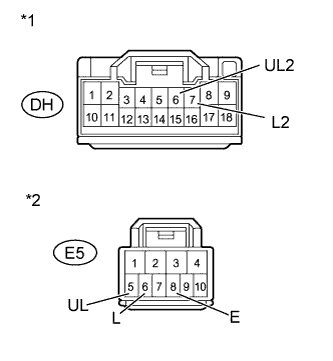
Text in Illustration *1 Front view of wire harness connector
(to Main body ECU)
*2 Component without harness connected
(to Front Door Lock)
for LHD:
-
Disconnect the E16 door lock connector.
-
Disconnect the DH ECU connector.
-
Measure the resistance according to the value(s) in the table below.
Standard Resistance Tester Connection Condition Specified Condition E16-10 (UL) - DH-6 (UL2) Always Below 1 Ω E16-9 (L) - DH-7 (L2) Always Below 1 Ω E16-7 (E) - Body ground Always Below 1 Ω E16-10 (UL) - Body ground Always 10 kΩ or higher E16-9 (L) - Body ground Always 10 kΩ or higher
-
-
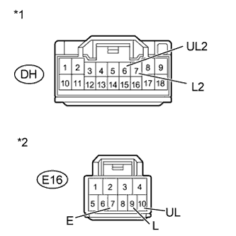
Text in Illustration *1 Front view of wire harness connector
(to Main body ECU)
*2 Component without harness connected
(to Front Door Lock)
for RHD:
-
Disconnect the E5 door lock connector.
-
Disconnect the DH ECU connector.
-
Measure the resistance according to the value(s) in the table below.
Standard Resistance Tester Connection Condition Specified Condition E5-5 (UL) - DH-6 (UL2) Always Below 1 Ω E5-6 (L) - DH-7 (L2) Always Below 1 Ω E5-8 (E) - Body ground Always Below 1 Ω E5-5 (UL) - Body ground Always 10 kΩ or higher E5-6 (L) - Body ground Always 10 kΩ or higher
-
NG
REPAIR OR REPLACE HARNESS OR CONNECTOR
OK
-
-
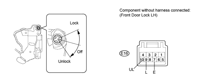
INSPECT FRONT DOOR LOCK ASSEMBLY (DOOR KEY-LINKED LOCK AND UNLOCK SWITCH)
-
for LHD:
-
Remove the front door lock (for Driver Side) Click here.
-
Measure the resistance according to the value(s) in the table below.
Standard Resistance Tester Connection Condition Specified Condition 9 (L) - 7 (E) Lock Below 1 Ω 9 (L) - 7 (E) Off 10 kΩ or higher 10 (UL) - 7 (E) Unlock Below 1 Ω 10 (UL) - 7 (E) Off 10 kΩ or higher
-
-
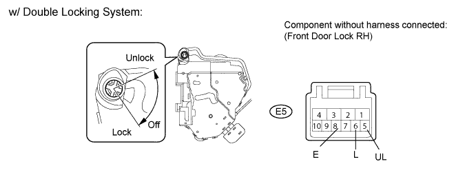
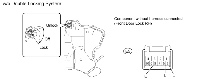
for RHD:
-
Remove the front door lock (for Driver Side) Click here.
-
Measure the resistance according to the value(s) in the table below.
Standard Resistance Tester Connection Condition Specified Condition 5 (UL) - 8 (E) Unlock Below 1 Ω 5 (UL) - 8 (E) Off 10 kΩ or higher 6 (L) - 8 (E) Lock Below 1 Ω 6 (L) - 8 (E) Off 10 kΩ or higher
-
NG
REPLACE FRONT DOOR LOCK ASSEMBLY Click here
OK
REPLACE MAIN BODY ECU (INSTRUMENT PANEL JUNCTION BLOCK ASSEMBLY)
-