CAN COMMUNICATION SYSTEM Short in CAN Bus Lines
DESCRIPTION
There may be a short circuit between the CAN bus lines when the resistance between terminals 6 (CANH) and 14 (CANL) of the DLC3 is below 54 Ω.
| Symptom | Trouble Area |
|---|---|
| The resistance between terminals 6 (CANH) and 14 (CANL) of the DLC3 is below 54 Ω. |
|
-
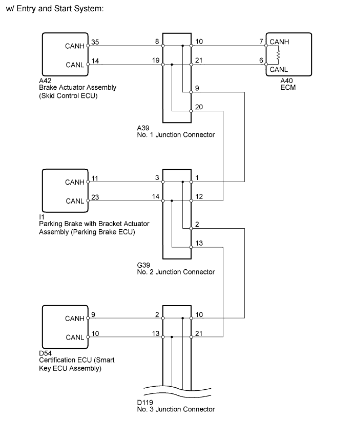
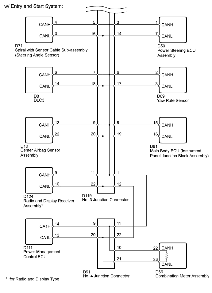
*1: w/ Entry and Start System
-
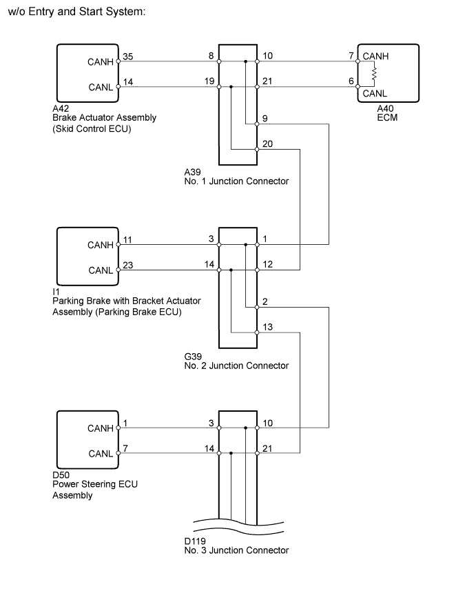
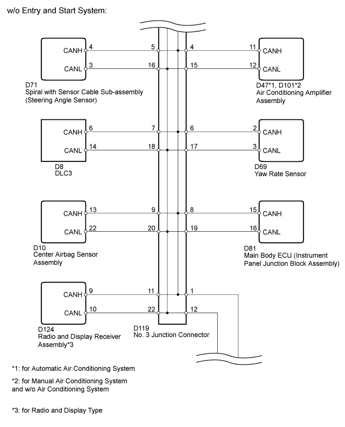
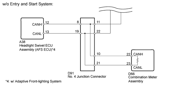
*2: w/o Entry and Start System
-
*3: for Radio and Display Type
-
*4: w/ Adaptive Front-lighting System and w/o Entry and Start System
WIRING DIAGRAM
INSPECTION PROCEDURE
Note
For vehicles with an entry and start system:
Before replacing the certification ECU (smart key ECU assembly), refer to the entry and start system (for Entry Function) Click here.
Tech Tips
Operating the ignition switch, any switches or any doors triggers related ECU and sensor communication with the CAN, which causes resistance variation.
PROCEDURE
-
PRECAUTION
Note
After turning the ignition switch off, waiting time may be required before disconnecting the cable from the battery terminal. Therefore, make sure to read the disconnecting the cable from the battery terminal notice before proceeding with work Click here.
NEXT 
-
DISCONNECT CABLE FROM NEGATIVE BATTERY TERMINAL
-
Disconnect the cable from the negative (-) battery terminal before measuring the resistances of the CAN main wire and the CAN branch wire
CAUTION:
Wait at least 90 seconds after disconnecting the cable from the negative (-) battery terminal to disable the SRS system.
Note
When disconnecting the cable, some systems need to be initialized after the cable is reconnected Click here.
NEXT
-
-
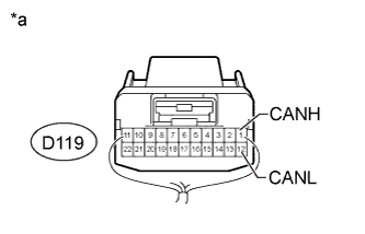
CHECK FOR SHORT IN CAN BUS WIRE (NO. 3 JUNCTION CONNECTOR - DLC3)
-
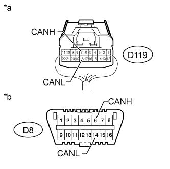
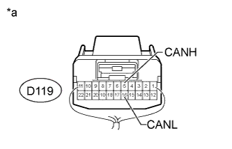
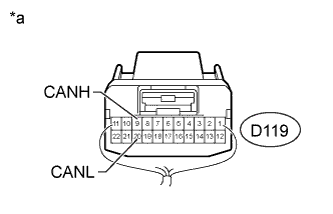
Text in Illustration *a Rear view of wire harness connector
(to No. 3 Junction Connector)
*b Front view of DLC3 Disconnect the D119 No. 3 junction connector.
-
Measure the resistance according to the value(s) in the table below.
Standard Resistance Tester Connection Switch Condition Specified Condition D119-7 (CANH) - D8-6 (CANH) Ignition switch off Below 1 Ω D119-18 (CANL) - D8-14 (CANL) Ignition switch off Below 1 Ω
NG 
REPAIR OR REPLACE CAN BRANCH WIRE CONNECTED TO DLC3 (CANH, CANL)
OK
-
-
CONNECT CONNECTOR
-
Reconnect the D119 No. 3 junction connector.
NEXT
-
-
CHECK FOR SHORT IN CAN BUS WIRE (NO. 1 JUNCTION CONNECTOR SIDE)
-
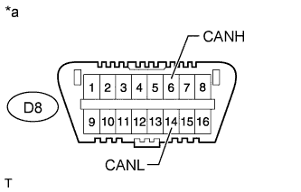
Text in Illustration *a Front view of DLC3 Disconnect the A39 No. 1 junction connector.
-
Measure the resistance according to the value(s) in the table below.
Standard Resistance Tester Connection Switch Condition Specified Condition D8-6 (CANH) - D8-14 (CANL) Ignition switch off 108 to 132 Ω
NG 
CONNECT CONNECTOR Click here
OK
-
-
CHECK FOR SHORT IN CAN BUS WIRE (NO. 1 JUNCTION CONNECTOR - SKID CONTROL ECU)
-
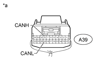
Text in Illustration *a Rear view of wire harness connector
(to No. 1 Junction Connector)
Measure the resistance according to the value(s) in the table below.
Standard Resistance Tester Connection Switch Condition Specified Condition A39-8 (CANH) - A39-19 (CANL) Ignition switch off 200 Ω or higher
NG
CONNECT CONNECTOR Click here
OK
-
-
CHECK FOR SHORT IN CAN BUS WIRE (NO. 1 JUNCTION CONNECTOR - ECM)
-
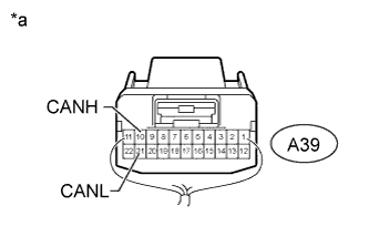
Text in Illustration *a Rear view of wire harness connector
(to No. 1 Junction Connector)
Measure the resistance according to the value(s) in the table below.
Standard Resistance Tester Connection Switch Condition Specified Condition A39-10 (CANH) - A39-21 (CANL) Ignition switch off 108 to 132 Ω
NG
CONNECT CONNECTOR Click here
OK 
REPLACE NO. 1 JUNCTION CONNECTOR
-
-
CONNECT CONNECTOR
-
Reconnect the A39 No. 1 junction connector.
NEXT
-
-
CHECK FOR SHORT IN CAN BUS WIRE (SKID CONTROL ECU)
-
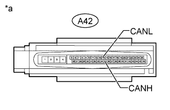
Text in Illustration *a Front view of wire harness connector
(to Brake Actuator Assembly [Skid Control ECU])
Disconnect the A42 brake actuator assembly (skid control ECU) connector.
-
Measure the resistance according to the value(s) in the table below.
Standard Resistance Tester Connection Switch Condition Specified Condition A42-35 (CANH) - A42-14 (CANL) Ignition switch off 54 to 69 Ω
NG
REPAIR OR REPLACE CAN BRANCH WIRE CONNECTED TO SKID CONTROL ECU (CANH, CANL)
OK
REPLACE BRAKE ACTUATOR ASSEMBLY (SKID CONTROL ECU) Click here
-
-
CONNECT CONNECTOR
-
Reconnect the A39 No. 1 junction connector.
NEXT
-
-
CHECK FOR SHORT IN CAN BUS WIRE (ECM)
-
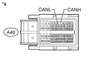
Text in Illustration *a Front view of wire harness connector
(to ECM)
Disconnect the A40 ECM connector.
-
Measure the resistance according to the value(s) in the table below.
Standard Resistance Tester Connection Switch Condition Specified Condition A40-7 (CANH) - A40-6 (CANL) Ignition switch off 108 to 132 Ω Result Result Proceed to OK (for 1AD-FTV) A OK (for 2AD-FTV) B OK (for 2AD-FHV) C NG D
B
REPLACE ECM Click here
C
REPLACE ECM Click here
D
REPAIR OR REPLACE CAN MAIN WIRE CONNECTED TO ECM (CANH, CANL)
A
REPLACE ECM Click here
-
-
CONNECT CONNECTOR
-
Reconnect the A39 No. 1 junction connector.
NEXT
-
-
CHECK FOR SHORT IN CAN BUS WIRE (NO. 2 JUNCTION CONNECTOR - NO. 1 JUNCTION CONNECTOR)
-
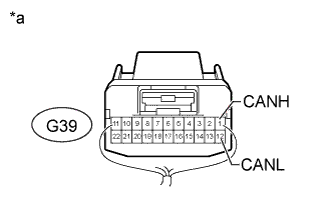
Text in Illustration *a Rear view of wire harness connector
(to No. 2 Junction Connector)
Disconnect the G39 No. 2 junction connector.
-
Measure the resistance according to the value(s) in the table below.
Standard Resistance Tester Connection Switch Condition Specified Condition G39-1 (CANH) - G39-12 (CANL) Ignition switch off 108 to 132 Ω
NG
REPAIR OR REPLACE CAN MAIN WIRE OR CONNECTOR (NO. 2 JUNCTION CONNECTOR - NO. 1 JUNCTION CONNECTOR)
OK
-
-
CHECK FOR SHORT IN CAN BUS WIRE (NO. 2 JUNCTION CONNECTOR SIDE)
-
Text in Illustration *a Front view of DLC3 Measure the resistance according to the value(s) in the table below.
Standard Resistance Tester Connection Switch Condition Specified Condition D8-6 (CANH) - D8-14 (CANL) Ignition switch off 108 to 132 Ω
NG
CONNECT CONNECTOR Click here
OK
-
-
CHECK FOR SHORT IN CAN BUS WIRE (NO. 2 JUNCTION CONNECTOR - PARKING BRAKE ECU)
-
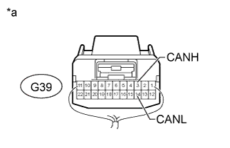
Text in Illustration *a Rear view of wire harness connector
(to No. 2 Junction Connector)
Measure the resistance according to the value(s) in the table below.
Standard Resistance Tester Connection Switch Condition Specified Condition G39-3 (CANH) - G39-14 (CANL) Ignition switch off 200 Ω or higher
NG
CONNECT CONNECTOR Click here
OK
REPLACE NO. 2 JUNCTION CONNECTOR
-
-
CONNECT CONNECTOR
-
Reconnect the G39 No. 2 junction connector.
NEXT
-
-
CHECK FOR SHORT IN CAN BUS WIRE (PARKING BRAKE ECU)
-
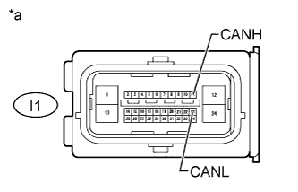
Text in Illustration *a Front view of wire harness connector
(to Parking Brake with Bracket Actuator Assembly [Parking Brake ECU])
Disconnect the I1 parking brake with bracket actuator assembly (parking brake ECU) connector.
-
Measure the resistance according to the value(s) in the table below.
Standard Resistance Tester Connection Switch Condition Specified Condition I1-11 (CANH) - I1-23 (CANL) Ignition switch off 54 to 69 Ω
NG
REPAIR OR REPLACE CAN BRANCH WIRE CONNECTED TO PARKING BRAKE ECU (CANH, CANL)
OK
REPLACE PARKING BRAKE WITH BRACKET ACTUATOR ASSEMBLY (PARKING BRAKE ECU) Click here
-
-
CONNECT CONNECTOR
-
Reconnect the G39 No. 2 junction connector.
NEXT
-
-
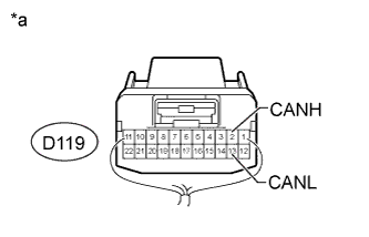
CHECK FOR SHORT IN CAN BUS WIRE (NO. 3 JUNCTION CONNECTOR - NO. 2 JUNCTION CONNECTOR)
-
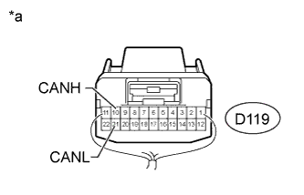
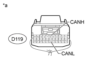
Text in Illustration *a Rear view of wire harness connector
(to No. 3 Junction Connector)
Disconnect the D119 No. 3 junction connector.
-
Measure the resistance according to the value(s) in the table below.
Standard Resistance Tester Connection Switch Condition Specified Condition D119-10 (CANH) - D119-21 (CANL) Ignition switch off 108 to 132 Ω
NG
REPAIR OR REPLACE CAN MAIN WIRE OR CONNECTOR (NO. 3 JUNCTION CONNECTOR - NO. 2 JUNCTION CONNECTOR)
OK
-
-
CONNECT CONNECTOR
-
Reconnect the D119 No. 3 junction connector.
NEXT
-
-
CHECK FOR SHORT IN CAN BUS WIRE (NO. 4 JUNCTION CONNECTOR SIDE)
-
Text in Illustration *a Front view of DLC3 Disconnect the D91 No. 4 junction connector.
-
Measure the resistance according to the value(s) in the table below.
Standard Resistance Tester Connection Switch Condition Specified Condition D8-6 (CANH) - D8-14 (CANL) Ignition switch off 108 to 132 Ω
NG
CONNECT CONNECTOR Click here
OK
-
-
CHECK FOR SHORT IN CAN BUS WIRE (NO. 4 JUNCTION CONNECTOR - HEADLIGHT SWIVEL ECU ASSEMBLY)
Note
For vehicles without an adaptive front-lighting system and with an entry and start system, go to "Check for Short in CAN Bus Wire (No. 4 Junction Connector - Power Management Control ECU)".
-
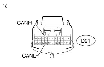
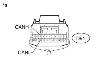
Text in Illustration *a Rear view of wire harness connector
(to No. 4 Junction Connector)
Measure the resistance according to the value(s) in the table below.
Standard Resistance Tester Connection Switch Condition Specified Condition D91-8 (CANH) - D91-19 (CANL) Ignition switch off 200 Ω or higher
NG
CONNECT CONNECTOR Click here
OK
-
-
CHECK FOR SHORT IN CAN BUS WIRE (NO. 4 JUNCTION CONNECTOR - POWER MANAGEMENT CONTROL ECU)
Note
For vehicles without an entry and start system, go to "Check for Short in CAN Bus Wire (No. 4 Junction Connector - Combination Meter Assembly)".
-
Text in Illustration *a Rear view of wire harness connector
(to No. 4 Junction Connector)
Measure the resistance according to the value(s) in the table below.
Standard Resistance Tester Connection Switch Condition Specified Condition D91-9 (CANH) - D91-20 (CANL) Ignition switch off 200 Ω or higher
NG
CONNECT CONNECTOR Click here
OK
-
-
CHECK FOR SHORT IN CAN BUS WIRE (NO. 4 JUNCTION CONNECTOR - COMBINATION METER ASSEMBLY)
-

Text in Illustration *a Rear view of wire harness connector
(to No. 4 Junction Connector)
Measure the resistance according to the value(s) in the table below.
Standard Resistance Tester Connection Switch Condition Specified Condition D91-10 (CANH) - D91-21 (CANL) Ignition switch off 108 to 132 Ω
NG
CONNECT CONNECTOR Click here
OK
REPLACE NO. 4 JUNCTION CONNECTOR
-
-
CONNECT CONNECTOR
-
Reconnect the D91 No. 4 junction connector.
NEXT
-
-
CHECK FOR SHORT IN CAN BUS WIRE (HEADLIGHT SWIVEL ECU ASSEMBLY)
-
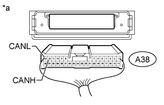
Text in Illustration *a Rear view of wire harness connector
(to Headlight Swivel ECU Assembly [AFS ECU])
Disconnect the A38 headlight swivel ECU assembly (AFS ECU) connector.
-
Measure the resistance according to the value(s) in the table below.
Standard Resistance Tester Connection Switch Condition Specified Condition A38-12 (CANH) - A38-13 (CANL) Ignition switch off 54 to 69 Ω
NG
REPAIR OR REPLACE CAN BRANCH WIRE CONNECTED TO HEADLIGHT SWIVEL ECU ASSEMBLY (CANH, CANL)
OK
REPLACE HEADLIGHT SWIVEL ECU ASSEMBLY (AFS ECU) Click here
-
-
CONNECT CONNECTOR
-
Reconnect the D91 No. 4 junction connector.
NEXT
-
-
CHECK FOR SHORT IN CAN BUS WIRE (POWER MANAGEMENT CONTROL ECU)
-
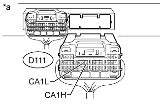
Text in Illustration *a Rear view of wire harness connector
(to Power Management Control ECU)
Disconnect the D111 power management control ECU connector.
-
Measure the resistance according to the value(s) in the table below.
Standard Resistance Tester Connection Switch Condition Specified Condition D111-14 (CA1H) - D111- 13 (CA1L) Ignition switch off 54 to 69 Ω
NG
REPAIR OR REPLACE CAN BRANCH WIRE CONNECTED TO POWER MANAGEMENT CONTROL ECU (CA1H, CA1L)
OK
REPLACE POWER MANAGEMENT CONTROL ECU Click here
-
-
CONNECT CONNECTOR
-
Reconnect the D91 No. 4 junction connector.
NEXT
-
-
CHECK FOR SHORT IN CAN BUS WIRE (COMBINATION METER ASSEMBLY)
-
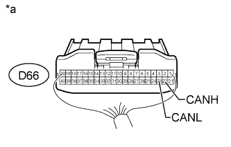
Text in Illustration *a Rear view of wire harness connector
(to Combination Meter Assembly)
Disconnect the D66 combination meter assembly connector.
-
Measure the resistance according to the value(s) in the table below.
Standard Resistance Tester Connection Switch Condition Specified Condition D66-22 (CANH) - D66-23 (CANL) Ignition switch off 108 to 132 Ω
NG
REPAIR OR REPLACE CAN MAIN WIRE CONNECTED TO COMBINATION METER ASSEMBLY (CANH, CANL)
OK
REPLACE COMBINATION METER ASSEMBLY Click here
-
-
CONNECT CONNECTOR
-
Reconnect the D91 No. 4 junction connector.
NEXT
-
-
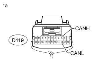
CHECK FOR SHORT IN CAN BUS WIRE (NO. 3 JUNCTION CONNECTOR - NO. 4 JUNCTION CONNECTOR)
-
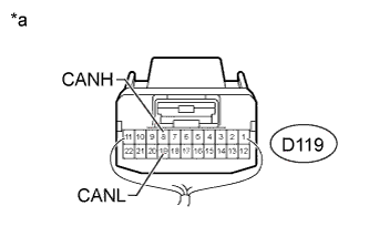
Text in Illustration *a Rear view of wire harness connector
(to No. 3 Junction Connector)
Disconnect the D119 No. 3 junction connector.
-
Measure the resistance according to the value(s) in the table below.
Standard Resistance Tester Connection Switch Condition Specified Condition D119-1 (CANH) - D119- 12 (CANL) Ignition switch off 108 to 132 Ω
NG
REPAIR OR REPLACE CAN MAIN WIRE OR CONNECTOR (NO. 3 JUNCTION CONNECTOR - NO. 4 JUNCTION CONNECTOR)
OK
-
-
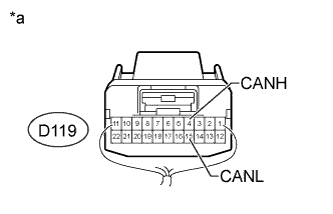
CHECK FOR SHORT IN CAN BUS WIRE (NO. 3 JUNCTION CONNECTOR - CERTIFICATION ECU)
Note
For vehicles without an entry and start system, go to "Check for Short in CAN Bus Wire (No. 3 Junction Connector - Power Steering ECU Assembly)".
-
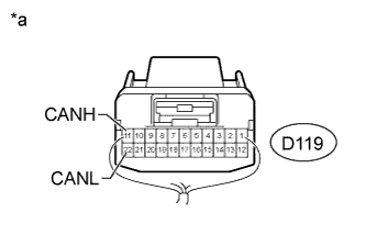
Text in Illustration *a Rear view of wire harness connector
(to No. 3 Junction Connector)
Measure the resistance according to the value(s) in the table below.
Standard Resistance Tester Connection Switch Condition Specified Condition D119-2 (CANH) - D119-13 (CANL) Ignition switch off 200 Ω or higher
NG
CONNECT CONNECTOR Click here
OK
-
-
CHECK FOR SHORT IN CAN BUS WIRE (NO. 3 JUNCTION CONNECTOR - POWER STEERING ECU ASSEMBLY)
-
Text in Illustration *a Rear view of wire harness connector
(to No. 3 Junction Connector)
Measure the resistance according to the value(s) in the table below.
Standard Resistance Tester Connection Switch Condition Specified Condition D119-3 (CANH) - D119-14 (CANL) Ignition switch off 200 Ω or higher
NG
CONNECT CONNECTOR Click here
OK
-
-
CHECK FOR SHORT IN CAN BUS WIRE (NO. 3 JUNCTION CONNECTOR - AIR CONDITIONING AMPLIFIER ASSEMBLY)
Note
For vehicles with an entry and start system, go to "Check for Short in CAN Bus Wire (No. 3 Junction Connector - Steering Angle Sensor)".
-
Text in Illustration *a Rear view of wire harness connector
(to No. 3 Junction Connector)
Measure the resistance according to the value(s) in the table below.
Standard Resistance Tester Connection Switch Condition Specified Condition D119-4 (CANH) - D119-15 (CANL) Ignition switch off 200 Ω or higher
NG
CONNECT CONNECTOR Click here
OK
-
-
CHECK FOR SHORT IN CAN BUS WIRE (NO. 3 JUNCTION CONNECTOR - STEERING ANGLE SENSOR)
-
Text in Illustration *a Rear view of wire harness connector
(to No. 3 Junction Connector)
Measure the resistance according to the value(s) in the table below.
Standard Resistance Tester Connection Switch Condition Specified Condition D119-5 (CANH) - D119-16 (CANL) Ignition switch off 200 Ω or higher
NG
CONNECT CONNECTOR Click here
OK
-
-
CHECK FOR SHORT IN CAN BUS WIRE (NO. 3 JUNCTION CONNECTOR - YAW RATE SENSOR)
-
Text in Illustration *a Rear view of wire harness connector
(to No. 3 Junction Connector)
Measure the resistance according to the value(s) in the table below.
Standard Resistance Tester Connection Switch Condition Specified Condition D119-6 (CANH) - D119-17 (CANL) Ignition switch off 200 Ω or higher
NG
CONNECT CONNECTOR Click here
OK
-
-
CHECK FOR SHORT IN CAN BUS WIRE (NO. 3 JUNCTION CONNECTOR - MAIN BODY ECU)
-
Text in Illustration *a Rear view of wire harness connector
(to No. 3 Junction Connector)
Measure the resistance according to the value(s) in the table below.
Standard Resistance Tester Connection Switch Condition Specified Condition D119-8 (CANH) - D119-19 (CANL) Ignition switch off 200 Ω or higher
NG
CONNECT CONNECTOR Click here
OK
-
-
CHECK FOR SHORT IN CAN BUS WIRE (NO. 3 JUNCTION CONNECTOR - RADIO AND DISPLAY RECEIVER ASSEMBLY)
Note
For vehicles without an radio and display type, go to "Check for Short in CAN Bus Wire (No. 3 Junction Connector - Center Airbag Sensor Assembly)".
-
Text in Illustration *a Rear view of wire harness connector
(to No. 3 Junction Connector)
Measure the resistance according to the value(s) in the table below.
Standard Resistance Tester Connection Switch Condition Specified Condition D119-11 (CANH) - D119-22 (CANL) Ignition switch off 200 Ω or higher
NG
CONNECT CONNECTOR Click here
OK
-
-
CHECK FOR SHORT IN CAN BUS WIRE (NO. 3 JUNCTION CONNECTOR - CENTER AIRBAG SENSOR ASSEMBLY)
-
Text in Illustration *a Rear view of wire harness connector
(to No. 3 Junction Connector)
Measure the resistance according to the value(s) in the table below.
Standard Resistance Tester Connection Switch Condition Specified Condition D119-9 (CANH) - D119-20 (CANL) Ignition switch off 200 Ω or higher
NG
CONNECT CONNECTOR Click here
OK
REPLACE NO. 3 JUNCTION CONNECTOR
-
-
CONNECT CONNECTOR
-
Reconnect the D119 No. 3 junction connector.
NEXT
-
-
CHECK FOR SHORT IN CAN BUS WIRE (CERTIFICATION ECU)
-
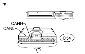
Text in Illustration *a Rear view of wire harness connector
(to Certification ECU [Smart Key ECU Assembly])
Disconnect the D54 certification ECU (smart key ECU assembly) connector.
-
Measure the resistance according to the value(s) in the table below.
Standard Resistance Tester Connection Switch Condition Specified Condition D54-9 (CANH) - D54-10 (CANL) Ignition switch off 54 to 69 Ω
NG
REPAIR OR REPLACE CAN BRANCH WIRE CONNECTED TO CERTIFICATION ECU (CANH, CANL)
OK
REPLACE CERTIFICATION ECU (SMART KEY ECU ASSEMBLY)
-
-
CONNECT CONNECTOR
-
Reconnect the D119 No. 3 junction connector.
NEXT
-
-
CHECK FOR SHORT IN CAN BUS WIRE (POWER STEERING ECU ASSEMBLY)
-
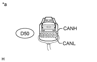
Text in Illustration *a Rear view of wire harness connector
(to Power Steering ECU Assembly)
Disconnect the D50 power steering ECU assembly connector.
-
Measure the resistance according to the value(s) in the table below.
Standard Resistance Tester Connection Switch Condition Specified Condition D50-1 (CANH) - D50-7 (CANL) Ignition switch off 54 to 69 Ω Result Result Proceed to OK (for LHD) A OK (for RHD) B NG C
B
REPLACE POWER STEERING ECU ASSEMBLY Click here
C
REPAIR OR REPLACE CAN BRANCH WIRE CONNECTED TO POWER STEERING ECU ASSEMBLY (CANH, CANL)
A
REPLACE POWER STEERING ECU ASSEMBLY Click here
-
-
CONNECT CONNECTOR
-
Reconnect the D119 No. 3 junction connector.
NEXT
-
-
CHECK FOR SHORT IN CAN BUS WIRE (AIR CONDITIONING AMPLIFIER ASSEMBLY)
-
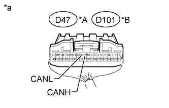
Text in Illustration *A for Automatic Air Conditioning System *B for Manual Air Conditioning System and w/o Air Conditioning System *a Rear view of wire harness connector
(to Air Conditioning Amplifier Assembly)
Disconnect the D47*1 or D101*2 air conditioning amplifier assembly connector.
-
*1: for Automatic Air Conditioning System
-
*2: for Manual Air Conditioning System and w/o Air Conditioning System
-
-
Measure the resistance according to the value(s) in the table below.
Standard Resistance for Automatic Air Conditioning System Tester Connection Switch Condition Specified Condition D47-11 (CANH) - D47-12 (CANL) Ignition switch off 54 to 69 Ω for Manual Air Conditioning System and w/o Air Conditioning System Tester Connection Switch Condition Specified Condition D101-11 (CANH) - D101-12 (CANL) Ignition switch off 54 to 69 Ω
NG
REPAIR OR REPLACE CAN BRANCH WIRE CONNECTED TO AIR CONDITIONING AMPLIFIER ASSEMBLY (CANH, CANL)
OK
REPLACE AIR CONDITIONING AMPLIFIER ASSEMBLY Click here
-
-
CONNECT CONNECTOR
-
Reconnect the D119 No. 3 junction connector.
NEXT
-
-
CHECK FOR SHORT IN CAN BUS WIRE (STEERING ANGLE SENSOR)
-
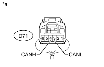
Text in Illustration *a Rear view of wire harness connector
(to Spiral with Sensor Cable Sub-assembly [Steering Angle Sensor])
Disconnect the D71 spiral with sensor cable sub-assembly (steering angle sensor) connector.
-
Measure the resistance according to the value(s) in the table below.
Standard Resistance Tester Connection Switch Condition Specified Condition D71-4 (CANH) - D71-3 (CANL) Ignition switch off 54 to 69 Ω
NG
REPAIR OR REPLACE CAN BRANCH WIRE CONNECTED TO STEERING ANGLE SENSOR (CANH, CANL)
OK
REPLACE SPIRAL WITH SENSOR CABLE SUB-ASSEMBLY (STEERING ANGLE SENSOR) Click here
-
-
CONNECT CONNECTOR
-
Reconnect the D119 No. 3 junction connector.
NEXT
-
-
CHECK FOR SHORT IN CAN BUS WIRE (YAW RATE SENSOR)
-
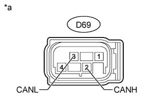
Text in Illustration *a Front view of wire harness connector
(to Yaw Rate Sensor)
Disconnect the D69 yaw rate sensor connector.
-
Measure the resistance according to the value(s) in the table below.
Standard Resistance Tester Connection Switch Condition Specified Condition D69-2 (CANH) - D69-3 (CANL) Ignition switch off 54 to 69 Ω
NG
REPAIR OR REPLACE CAN BRANCH WIRE CONNECTED TO YAW RATE SENSOR (CANH, CANL)
OK
REPLACE YAW RATE SENSOR Click here
-
-
CONNECT CONNECTOR
-
Reconnect the D119 No. 3 junction connector.
NEXT
-
-
CHECK FOR SHORT IN CAN BUS WIRE (MAIN BODY ECU)
-
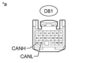
Text in Illustration *a Front view of wire harness connector
(to Main Body ECU [Instrument Panel Junction Block Assembly])
Disconnect the D81 main body ECU (instrument panel junction block assembly) connector.
-
Measure the resistance according to the value(s) in the table below.
Standard Resistance Tester Connection Switch Condition Specified Condition D81-15 (CANH) - D81-16 (CANL) Ignition switch off 54 to 69 Ω
NG
REPAIR OR REPLACE CAN BRANCH WIRE CONNECTED TO MAIN BODY ECU (CANH, CANL)
OK
REPLACE MAIN BODY ECU (INSTRUMENT PANEL JUNCTION BLOCK ASSEMBLY)
-
-
CONNECT CONNECTOR
-
Reconnect the D119 No. 3 junction connector.
NEXT
-
-
CHECK FOR SHORT IN CAN BUS WIRE (RADIO AND DISPLAY RECEIVER ASSEMBLY)
-
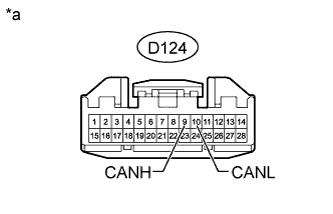
Text in Illustration *a Front view of wire harness connector
(to Radio and Display Receiver Assembly)
Disconnect the D124 radio and display receiver assembly connector.
-
Measure the resistance according to the value(s) in the table below.
Standard Resistance Tester Connection Switch Condition Specified Condition D124-9 (CANH) - D124-10 (CANL) Ignition switch off 54 to 69 Ω
NG
REPAIR OR REPLACE CAN BRANCH WIRE CONNECTED TO RADIO AND DISPLAY RECEIVER ASSEMBLY (CANH, CANL)
OK
REPLACE RADIO AND DISPLAY RECEIVER ASSEMBLY Click here
-
-
CONNECT CONNECTOR
-
Reconnect the D119 No. 3 junction connector.
NEXT
-
-
CHECK FOR SHORT IN CAN BUS WIRE (CENTER AIRBAG SENSOR ASSEMBLY)
-
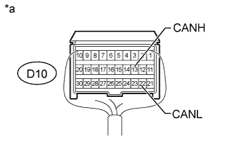
Text in Illustration *a Rear view of wire harness connector
(to Center Airbag Sensor Assembly)
Disconnect the D10 center airbag sensor assembly connector.
-
Measure the resistance according to the value(s) in the table below.
Standard Resistance Tester Connection Switch Condition Specified Condition D10-13 (CANH) - D10-22 (CANL) Ignition switch off 54 to 69 Ω
NG
REPAIR OR REPLACE CAN BRANCH WIRE CONNECTED TO CENTER AIRBAG SENSOR ASSEMBLY (CANH, CANL)
OK
REPLACE CENTER AIRBAG SENSOR ASSEMBLY Click here
-