CAN COMMUNICATION SYSTEM TERMINALS OF ECU

Tech Tips
Operating the ignition switch, any switches or any doors triggers related ECU and sensor communication with the CAN, which causes resistance variation.
-
DISCONNECT CABLE FROM NEGATIVE BATTERY TERMINAL
-
Disconnect the cable from the negative (-) battery terminal before measuring the resistances of the CAN main wire and the CAN branch wire.
CAUTION:
Wait at least 90 seconds after disconnecting the cable from the negative (-) battery terminal to disable the SRS system.
Note
-
Before measuring the resistance, leave the vehicle for at least 1 minute and do not operate the ignition switch, any switches or any doors. If doors need to be opened in order to check connectors, open the doors and leave them open.
-
After turning the ignition switch off, waiting time may be required before disconnecting the cable from the battery terminal. Therefore, make sure to read the disconnecting the cable from the battery terminal notice before proceeding with work Click here.
-
When disconnecting the cable, some systems need to be initialized after the cable is reconnected Click here.
-
-
-
JUNCTION CONNECTOR
-
NO. 1 JUNCTION CONNECTOR
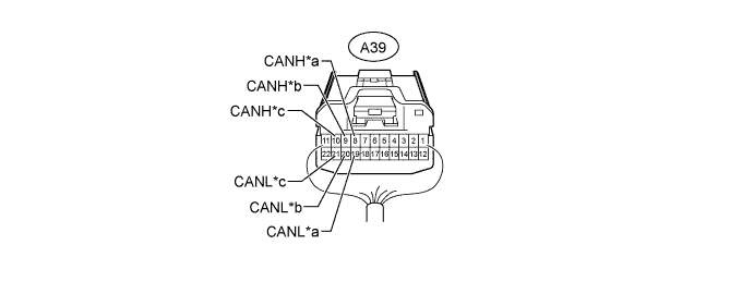
Text in Illustration *a for Brake Actuator Assembly (Skid Control ECU) *b for No. 2 Junction Connector *c for ECM (V1 Bus) - - No. 1 Junction Connector Wiring Color Connect to A39-8 (CANH) R Brake actuator assembly (skid control ECU) A39-19 (CANL) W A39-9 (CANH) B No. 2 junction connector A39-20 (CANL) W A39-10 (CANH) Y ECM (V1 bus) A39-21 (CANL) W -
NO. 2 JUNCTION CONNECTOR

Text in Illustration *a for No. 1 Junction Connector *b for No. 3 Junction Connector *c for Parking Brake with Bracket Actuator Assembly (Parking Brake ECU) - - No. 2 Junction Connector Wiring Color Connect to G39-1 (CANH) B No. 1 junction connector G39-12 (CANL) W G39-2 (CANH) G No. 3 junction connector G39-13 (CANL) W G39-3 (CANH) P Parking brake with bracket actuator assembly (parking brake ECU) G39-14 (CANL) W -
NO. 3 JUNCTION CONNECTOR
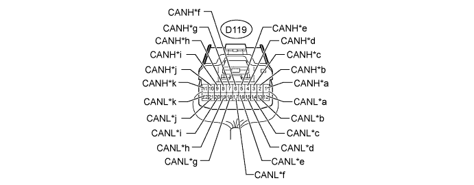
Text in Illustration *a for No. 4 Junction Connector (V1 Bus) *b for Certification ECU (Smart Key ECU Assembly) (w/ Entry and Start System) *c for Power Steering ECU Assembly *d for Air Conditioning Amplifier Assembly (w/o Entry and Start System) *e for Spiral with Sensor Cable Sub-assembly (Steering Angle Sensor) *f for Yaw Rate Sensor *g for DLC3 *h for Main Body ECU (Instrument Panel Junction Block Assembly) (V1 Bus) *i for Center Airbag Sensor Assembly *j for No. 2 Junction Connector *k for Radio and Display Receiver Assembly (for Radio and Display Type) - - No. 3 Junction Connector Wiring Color Connect to D119-1 (CANH) B No. 4 junction connector (V1 bus) D119-12 (CANL) W D119-2 (CANH) P Certification ECU (smart key ECU assembly)*1 D119-13 (CANL) W D119-3 (CANH) L Power steering ECU assembly D119-14 (CANL) W D119-4 (CANH) V Air conditioning amplifier assembly*2 D119-15 (CANL) W D119-5 (CANH) BR Spiral with sensor cable sub-assembly (steering angle sensor) D119-16 (CANL) W D119-6 (CANH) LG Yaw rate sensor D119-17 (CANL) W D119-7 (CANH) L DLC3 D119-18 (CANL) W D119-8 (CANH) R Main body ECU (instrument panel junction block assembly) (V1 bus) D119-19 (CANL) W D119-9 (CANH) B Center airbag sensor assembly D119-20 (CANL) W D119-10 (CANH) G No. 2 junction connector D119-21 (CANL) W D119-11 (CANH) SB Radio and display receiver assembly*3 D119-22 (CANL) W
-
*1: w/ Entry and Start System
-
*2: w/o Entry and Start System
-
*3: for Radio and Display Type
-
-
NO. 4 JUNCTION CONNECTOR
-
V1 Bus
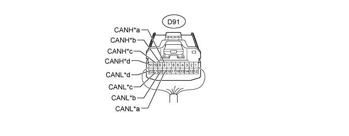
Text in Illustration *a for Headlight Swivel ECU Assembly (AFS ECU) (w/ Adaptive Front-lighting System and w/o Entry and Start System) *b for Power Management Control ECU (w/ Entry and Start System) *c for Combination Meter Assembly d for No. 3 Junction Connector No. 4 Junction Connector Wiring Color Connect to D91-8 (CANH) Y Headlight swivel ECU assembly (AFS ECU)*1 D91-19 (CANL) W D91-9 (CANH) G Power management control ECU*2 D91-20 (CANL) W D91-10 (CANH) L Combination meter assembly D91-21 (CANL) W D91-11 (CANH) B No. 3 junction connector D91-22 (CANL) W
-
*1: w/ Adaptive Front-lighting System and w/o Entry and Start System
-
*2: w/ Entry and Start System
-
-
Power Management Bus (w/ Entry and Start System)
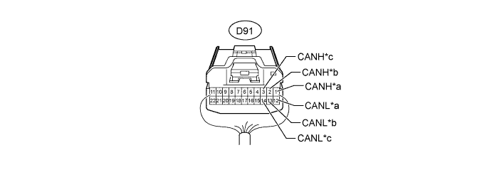
Text in Illustration *a for Air Conditioning Amplifier Assembly (for Automatic Air Conditioning System) *b for Power Management Control ECU *c for ECM - - No. 4 Junction Connector Wiring Color Connect to D91-1 (CANH) V Air conditioning amplifier assembly D91-12 (CANL) W D91-2 (CANH) L Power management control ECU D91-13 (CANL) W D91-3 (CANH) R ECM D91-14 (CANL) W
-
-
NO. 5 JUNCTION CONNECTOR (for Power Tilt and Power Telescopic Steering Column)
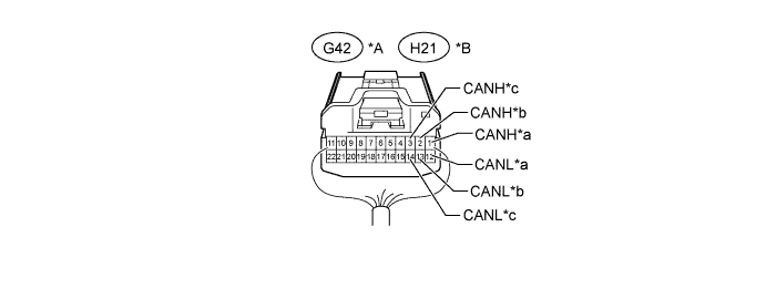
Text in Illustration *A for LHD *B for RHD *a for Position Control ECU Assembly (w/ Seat Position Memory System) *b for Multiplex Tilt and Telescopic ECU *c for Main Body ECU (Instrument Panel Junction Block Assembly) (MS Bus) - - for LHD No. 5 Junction Connector Wiring Color Connect to G42-1 (CANH) SB Position control ECU assembly* G42-12 (CANL) W G42-2 (CANH) G Multiplex tilt and telescopic ECU G42-13 (CANL) W G42-3 (CANH) R Main body ECU (instrument panel junction block assembly) (MS bus) G42-14 (CANL) W for RHD No. 5 Junction Connector Wiring Color Connect to H21-1 (CANH) SB Position control ECU assembly* H21-12 (CANL) W H21-2 (CANH) G Multiplex tilt and telescopic ECU H21-13 (CANL) W H21-3 (CANH) R Main body ECU (instrument panel junction block assembly) (MS bus) H21-14 (CANL) W
-
*: w/ Seat Position Memory System
-
-
NO. 6 JUNCTION CONNECTOR (w/ Dynamic Radar Cruise Control System)
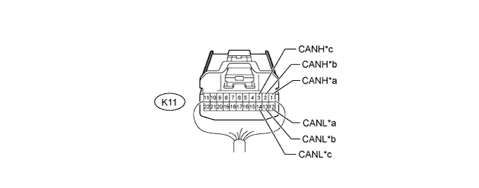
Text in Illustration *a for Millimeter Wave Radar Sensor Assembly *b for Driving Support ECU Assembly (Parking Assist Bus) *c for Lane Recognition Camera Sensor Assembly (w/ Lane-keeping Assist System) - - No. 6 Junction Connector Wiring Color Connect to K11-1 (CANH) B Millimeter wave radar sensor assembly K11-12 (CANL) W K11-2 (CANH) R Driving support ECU assembly (parking assist bus) K11-13 (CANL) W K11-3 (CANH) LG Lane recognition camera sensor assembly* K11-14 (CANL) W
-
*: w/ Lane-keeping Assist System
-
-
CAN JUNCTION CONNECTOR (w/ Entry and Start System)
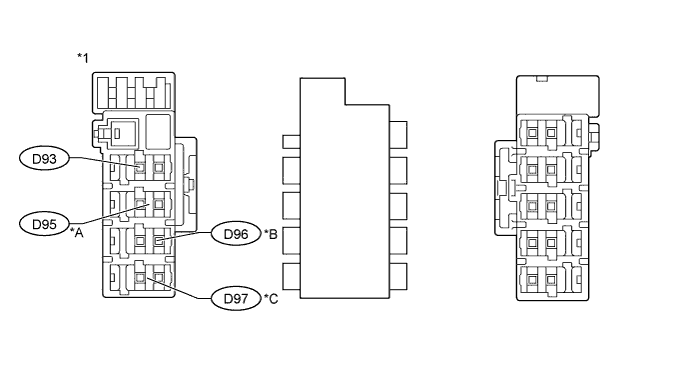
Text in Illustration *A w/ Adaptive Front-lighting System *B w/ Pre-crash Safety System *C w/ Dynamic Radar Cruise Control System - - *1 Junction Connector A Side - - Junction Connector A Side Wiring Color (CANH Side) Wiring Color (CANL Side) Power management control ECU (V2 bus) (D93) B W Headlight swivel ECU assembly (AFS ECU) (D95)*1 Y W Seat belt control ECU (D96)*2 G W Driving support ECU assembly (V2 bus) (D97)*3 L W
-
*1: w/ Adaptive Front-lighting System
-
*2: w/ Pre-crash Safety System
-
*3: w/ Dynamic Radar Cruise Control System
-
-
-
TERMINALS OF CONNECTORS FOR JUNCTION CONNECTOR (CAN JUNCTION CONNECTOR)
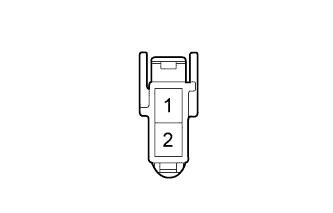
Terminal No. Symbol 1 CANH 2 CANL -
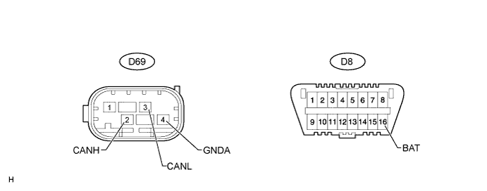
CHECK DLC3
-
Disconnect the cable from the negative (-) battery terminal before measuring the resistances of the CAN main wire and the CAN branch wire.
CAUTION:
Wait at least 90 seconds after disconnecting the cable from the negative (-) battery terminal to disable the SRS system.
Note
-
When disconnecting the cable, some systems need to be initialized after the cable is reconnected Click here.
-
After turning the ignition switch off, waiting time may be required before disconnecting the cable from the battery terminal. Therefore, make sure to read the disconnecting the cable from the battery terminal notice before proceeding with work Click here.
-
-
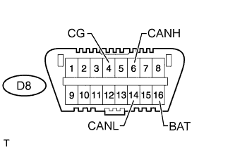
Measure the resistance according to the value(s) in the table below.
Terminal No. (Symbol) Wiring Color Switch Condition Specified Condition D8-6 (CANH) - D8-14 (CANL) L - W Ignition switch off 54 to 69 Ω D8-6 (CANH) - D8-4 (CG) L - W-B Ignition switch off 200 Ω or higher D8-14 (CANL) - D8-4 (CG) W - W-B Ignition switch off 200 Ω or higher D8-6 (CANH) - D8-16 (BAT) L - G Ignition switch off 6 kΩ or higher D8-14 (CANL) - D8-16 (BAT) W - G Ignition switch off 6 kΩ or higher
-
-
CHECK ECM
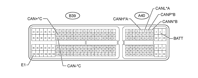
Text in Illustration *A V1 Bus *B Power Management Bus *C Powertrain Bus - -
-
Disconnect the A40 and B39 ECM connectors.
-
Measure the resistance according to the value(s) in the table below.
for V1 Bus Terminal No. (Symbol) Wiring Color Switch Condition Specified Condition A40-7 (CANH) - A40-6 (CANL) Y - W Ignition switch off 108 to 132 Ω A40-7 (CANH) - B39-109 (E1) Y - BR Ignition switch off 200 Ω or higher A40-6 (CANL) - B39-109 (E1) W - BR Ignition switch off 200 Ω or higher A40-7 (CANH) - A40-2 (BATT) Y - B Ignition switch off 6 kΩ or higher A40-6 (CANL) - A40-2 (BATT) W - B Ignition switch off 6 kΩ or higher for Power Management Bus Terminal No. (Symbol) Wiring Color Switch Condition Specified Condition A40-5 (CANP) - A40-4 (CANN) W - R Ignition switch off 108 to 132 Ω A40-5 (CANP) - B39-109 (E1) W - BR Ignition switch off 200 Ω or higher A40-4 (CANN) - B39-109 (E1) R - BR Ignition switch off 200 Ω or higher A40-5 (CANP) - A40-2 (BATT) W - B Ignition switch off 6 kΩ or higher A40-4 (CANN) - A40-2 (BATT) R - B Ignition switch off 6 kΩ or higher for Powertrain Bus Terminal No. (Symbol) Wiring Color Switch Condition Specified Condition B39-40 (CAN+) - B39-63 (CAN-) L - W Ignition switch off 108 to 132 Ω B39-40 (CAN+) - B39-109 (E1) L - BR Ignition switch off 200 Ω or higher B39-63 (CAN-) - B39-109 (E1) W - BR Ignition switch off 200 Ω or higher B39-40 (CAN+) - A40-2 (BATT) L - B Ignition switch off 6 kΩ or higher B39-63 (CAN-) - A40-2 (BATT) W - B Ignition switch off 6 kΩ or higher
-
-
CHECK POWER MANAGEMENT CONTROL ECU (w/ Entry and Start System)
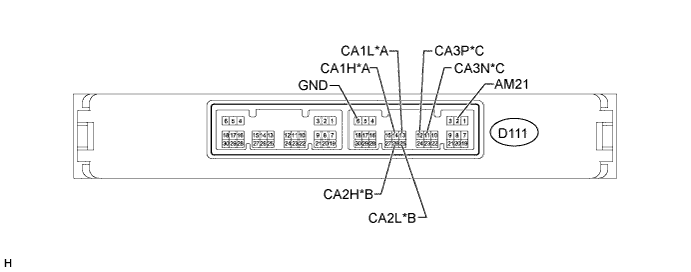
Text in Illustration *A V1 Bus *B V2 Bus *C Power Management Bus - -
-
Disconnect the D111 power management control ECU connector.
-
Measure the resistance according to the value(s) in the table below.
for V1 Bus Terminal No. (Symbol) Wiring Color Switch Condition Specified Condition D111-14 (CA1H) - D111-13 (CA1L) G - W Ignition switch off 54 to 69 Ω D111-14 (CA1H) - D111-6 (GND) G - W-B Ignition switch off 200 Ω or higher D111-13 (CA1L) - D111-6 (GND) W - W-B Ignition switch off 200 Ω or higher D111-14 (CA1H) - D111-2 (AM21) G - W Ignition switch off 6 kΩ or higher D111-13 (CA1L) - D111-2 (AM21) W - W Ignition switch off 6 kΩ or higher for V2 Bus Terminal No. (Symbol) Wiring Color Switch Condition Specified Condition D111-26 (CA2H) - D111-25 (CA2L) B - W Ignition switch off 108 to 132 Ω D111-26 (CA2H) - D111-6 (GND) B - W-B Ignition switch off 200 Ω or higher D111-25 (CA2L) - D111-6 (GND) W - W-B Ignition switch off 200 Ω or higher D111-26 (CA2H) - D111-2 (AM21) B - W Ignition switch off 6 kΩ or higher D111-25 (CA2L) - D111-2 (AM21) W - W Ignition switch off 6 kΩ or higher for Power Management Bus Terminal No. (Symbol) Wiring Color Switch Condition Specified Condition D111-12 (CA3P) - D111-11 (CA3N) W - R Ignition switch off 108 to 132 Ω D111-12 (CA3P) - D111-6 (GND) W - W-B Ignition switch off 200 Ω or higher D111-11 (CA3N) - D111-6 (GND) R - W-B Ignition switch off 200 Ω or higher D111-12 (CA3P) - D111-2 (AM21) W - W Ignition switch off 6 kΩ or higher D111-11 (CA3N) - D111-2 (AM21) R - W Ignition switch off 6 kΩ or higher
-
-
CHECK POWER MANAGEMENT CONTROL ECU (w/o Entry and Start System)

-
Disconnect the D104 power management control ECU connector.
-
Measure the resistance according to the value(s) in the table below.
Terminal No. (Symbol) Wiring Color Switch Condition Specified Condition D104-4 (CA3P) - D104-3 (CA3N) W - R Ignition switch off 108 to 132 Ω D104-4 (CA3P) - D104-12 (GND) W - W-B Ignition switch off 200 Ω or higher D104-3 (CA3N) - D104-12 (GND) R - W-B Ignition switch off 200 Ω or higher D104-4 (CA3P) - D104-8 (AM21) W - W Ignition switch off 6 kΩ or higher D104-3 (CA3N) - D104-8 (AM21) R - W Ignition switch off 6 kΩ or higher
-
-
CHECK MAIN BODY ECU (INSTRUMENT PANEL JUNCTION BLOCK ASSEMBLY)
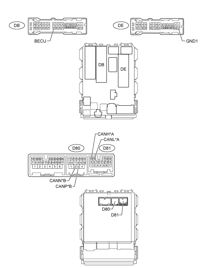
Text in Illustration *A V1 Bus *B MS Bus
-
Disconnect the D80, D81, DB and DE main body ECU (instrument panel junction block assembly) connectors.
-
Measure the resistance according to the value(s) in the table below.
for V1 Bus Terminal No. (Symbol) Wiring Color Switch Condition Specified Condition D81-15 (CANH) - D81-16 (CANL) R - W Ignition switch off 54 to 69 Ω D81-15 (CANH) - DE-17 (GND1) R - W-B Ignition switch off 200 Ω or higher D81-16 (CANL) - DE-17 (GND1) W - W-B Ignition switch off 200 Ω or higher D81-15 (CANH) - DB-30 (BECU) R - W Ignition switch off 6 kΩ or higher D81-16 (CANL) - DB-30 (BECU) W - W Ignition switch off 6 kΩ or higher for MS Bus Terminal No. (Symbol) Wiring Color Switch Condition Specified Condition D80-3 (CANP) - D80-2 (CANN) R - W Ignition switch off 108 to 132 Ω D80-3 (CANP) - DE-17 (GND1) R - W-B Ignition switch off 200 Ω or higher D80-2 (CANN) - DE-17 (GND1) W - W-B Ignition switch off 200 Ω or higher D80-3 (CANP) - DB-30 (BECU) R - W Ignition switch off 6 kΩ or higher D80-2 (CANN) - DB-30 (BECU) W - W Ignition switch off 6 kΩ or higher
-
-
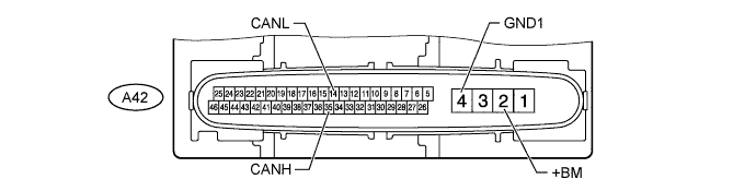
CHECK BRAKE ACTUATOR ASSEMBLY (SKID CONTROL ECU)
-
Disconnect the A42 brake actuator assembly (skid control ECU) connector.
-
Measure the resistance according to the value(s) in the table below.
Terminal No. (Symbol) Wiring Color Switch Condition Specified Condition A42-35 (CANH) - A42-14 (CANL) R - W Ignition switch off 54 to 69 Ω A42-35 (CANH) - A42-4 (GND1) R - W-B Ignition switch off 200 Ω or higher A42-14 (CANL) - A42-4 (GND1) W - W-B Ignition switch off 200 Ω or higher A42-35 (CANH) - A42-2 (+BM) R - L Ignition switch off 6 kΩ or higher A42-14 (CANL) - A42-2 (+BM) W - L Ignition switch off 6 kΩ or higher
-
-
CHECK AIR CONDITIONING AMPLIFIER ASSEMBLY
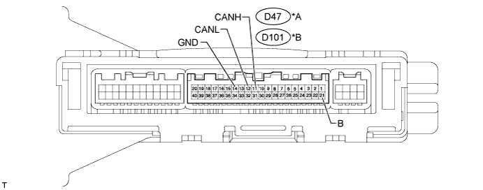
Text in Illustration *A for Automatic Air Conditioning System *B for Manual Air Conditioning System and w/o Air Conditioning System
-
Disconnect the D47*1 or D101*2 air conditioning amplifier assembly connector.
-
*1: for Automatic Air Conditioning System
-
*2: for Manual Air Conditioning System and w/o Air Conditioning System
-
-
Measure the resistance according to the value(s) in the table below.
for Automatic Air Conditioning System Terminal No. (Symbol) Wiring Color Switch Condition Specified Condition D47-11 (CANH) - D47-12 (CANL) V - W Ignition switch off 54 to 69 Ω D47-11 (CANH) - D47-14 (GND) V - W-B Ignition switch off 200 Ω or higher D47-12 (CANL) - D47-14 (GND) W - W-B Ignition switch off 200 Ω or higher D47-11 (CANH) - D47-21 (B) V - R Ignition switch off 6 kΩ or higher D47-12 (CANL) - D47-21 (B) W - R Ignition switch off 6 kΩ or higher for Manual Air Conditioning System and w/o Air Conditioning System Terminal No. (Symbol) Wiring Color Switch Condition Specified Condition D101-11 (CANH) - D101-12 (CANL) V - W Ignition switch off 54 to 69 Ω D101-11 (CANH) - D101-14 (GND) V - W-B Ignition switch off 200 Ω or higher D101-12 (CANL) - D101-14 (GND) W - W-B Ignition switch off 200 Ω or higher D101-11 (CANH) - D101-21 (B) V - R Ignition switch off 6 kΩ or higher D101-12 (CANL) - D101-21 (B) W - R Ignition switch off 6 kΩ or higher
-
-
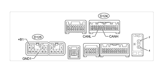
CHECK RADIO AND DISPLAY RECEIVER ASSEMBLY (for Radio and Display Type)
-
Disconnect the D124 and D125 radio and display receiver assembly connectors.
-
Measure the resistance according to the value(s) in the table below.
Terminal No. (Symbol) Wiring Color Switch Condition Specified Condition D124-9 (CANH) - D124-10 (CANL) SB - W Ignition switch off 54 to 69 Ω D124-9 (CANH) - D125-7 (GND1) SB - BR Ignition switch off 200 Ω or higher D124-10 (CANL) - D125-7 (GND1) W - BR Ignition switch off 200 Ω or higher D124-9 (CANH) - D125-4 (+B1) SB - SB Ignition switch off 6 kΩ or higher D124-10 (CANL) - D125-4 (+B1) W - SB Ignition switch off 6 kΩ or higher
-
-
CHECK COMBINATION METER ASSEMBLY

-
Disconnect the D66 combination meter assembly connector.
-
Measure the resistance according to the value(s) in the table below.
Terminal No. (Symbol) Wiring Color Switch Condition Specified Condition D66-22 (CANH) - D66-23 (CANL) L - W Ignition switch off 108 to 132 Ω D66-22 (CANH) - D66-21 (ET) L - W-B Ignition switch off 200 Ω or higher D66-23 (CANL) - D66-21 (ET) W - W-B Ignition switch off 200 Ω or higher D66-22 (CANH) - D66-40 (B) L - W Ignition switch off 6 kΩ or higher D66-23 (CANL) - D66-40 (B) W - W Ignition switch off 6 kΩ or higher
-
-
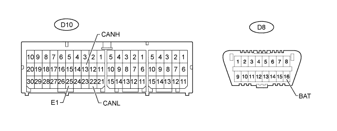
CHECK CENTER AIRBAG SENSOR ASSEMBLY
-
Disconnect the D10 center airbag sensor assembly connector.
-
Measure the resistance according to the value(s) in the table below.
Terminal No. (Symbol) Wiring Color Switch Condition Specified Condition D10-13 (CANH) - D10-22 (CANL) B - W Ignition switch off 54 to 69 Ω D10-13 (CANH) - D10-25 (E1) B - W-B Ignition switch off 200 Ω or higher D10-22 (CANL) - D10-25 (E1) W - W-B Ignition switch off 200 Ω or higher D10-13 (CANH) - D8-16 (BAT) B - G Ignition switch off 6 kΩ or higher D10-22 (CANL) - D8-16 (BAT) W - G Ignition switch off 6 kΩ or higher
-
-
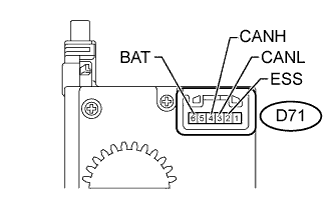
CHECK SPIRAL WITH SENSOR CABLE SUB-ASSEMBLY (STEERING ANGLE SENSOR)
-
Disconnect the D71 spiral with sensor cable sub-assembly (steering angle sensor) connector.
-
Measure the resistance according to the value(s) in the table below.
Terminal No. (Symbol) Wiring Color Switch Condition Specified Condition D71-4 (CANH) - D71-3 (CANL) BR - W Ignition switch off 54 to 69 Ω D71-4 (CANH) - D71-2 (ESS) BR - BR Ignition switch off 200 Ω or higher D71-3 (CANL) - D71-2 (ESS) W - BR Ignition switch off 200 Ω or higher D71-4 (CANH) - D71-6 (BAT) BR - W Ignition switch off 6 kΩ or higher D71-3 (CANL) - D71-6 (BAT) W - W Ignition switch off 6 kΩ or higher
-
-
CHECK YAW RATE SENSOR
-
Disconnect the D69 yaw rate sensor connector.
-
Measure the resistance according to the value(s) in the table below.
Terminal No. (Symbol) Wiring Color Switch Condition Specified Condition D69-2 (CANH) - D69-3 (CANL) LG - W Ignition switch off 54 to 69 Ω D69-2 (CANH) - D69-4 (GNDA) LG - BR Ignition switch off 200 Ω or higher D69-3 (CANL) - D69-4 (GNDA) W - BR Ignition switch off 200 Ω or higher D69-2 (CANH) - D8-16 (BAT) LG - G Ignition switch off 6 kΩ or higher D69-3 (CANL) - D8-16 (BAT) W - G Ignition switch off 6 kΩ or higher
-
-
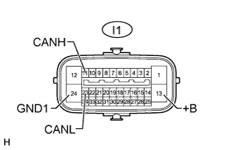
CHECK PARKING BRAKE WITH BRACKET ACTUATOR ASSEMBLY (PARKING BRAKE ECU)
-
Disconnect the I1 parking brake with bracket actuator assembly (parking brake ECU) connector.
-
Measure the resistance according to the value(s) in the table below.
Terminal No. (Symbol) Wiring Color Switch Condition Specified Condition I1-11 (CANH) - I1-23 (CANL) P - W Ignition switch off 54 to 69 Ω I1-11 (CANH) - I1-24 (GND1) P - W-B Ignition switch off 200 Ω or higher I1-23 (CANL) - I1-24 (GND1) W - W-B Ignition switch off 200 Ω or higher I1-11 (CANH) - I1-13 (+B) P - B Ignition switch off 6 kΩ or higher I1-23 (CANL) - I1-13 (+B) W - B Ignition switch off 6 kΩ or higher
-
-
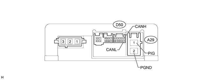
CHECK POWER STEERING ECU ASSEMBLY
-
Disconnect the A29 and D50 power steering assembly connectors.
-
Measure the resistance according to the value(s) in the table below.
Terminal No. (Symbol) Wiring Color Switch Condition Specified Condition D50-1 (CANH) - D50-7 (CANL) L - W Ignition switch off 54 to 69 Ω D50-1 (CANH) - A29-2 (PGND) L - W Ignition switch off 200 Ω or higher D50-7 (CANL) - A29-2 (PGND) W - W Ignition switch off 200 Ω or higher D50-1 (CANH) - A29-1 (PIG) L - B Ignition switch off 6 kΩ or higher D50-7 (CANL) - A29-1 (PIG) W - B Ignition switch off 6 kΩ or higher
-
-
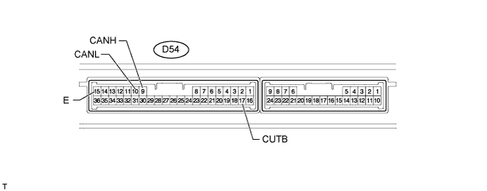
CHECK CERTIFICATION ECU (SMART KEY ECU ASSEMBLY ) (w/ Entry and Start System)
-
Disconnect the D54 certification ECU (smart key ECU assembly) connector.
-
Measure the resistance according to the value(s) in the table below.
Terminal No. (Symbol) Wiring Color Switch Condition Specified Condition D54-9 (CANH) - D54-10 (CANL) P - W Ignition switch off 54 to 69 Ω D54-9 (CANH) - D54-15 (E) P - W-B Ignition switch off 200 Ω or higher D54-10 (CANL) - D54-15 (E) W - W-B Ignition switch off 200 Ω or higher D54-9 (CANH) - D54-17 (CUTB) P - W Ignition switch off 6 kΩ or higher D54-10 (CANL) - D54-17 (CUTB) W - W Ignition switch off 6 kΩ or higher
-
-
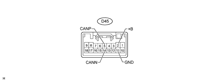
CHECK MULTIPLEX TILT AND TELESCOPIC ECU (for Power Tilt and Power Telescopic Steering Column)
-
Disconnect the D45 multiplex tilt and telescopic ECU connector.
-
Measure the resistance according to the value(s) in the table below.
Terminal No. (Symbol) Wiring Color Switch Condition Specified Condition D45-5 (CANP) - D45-14 (CANN) G - W Ignition switch off 108 to 132 Ω D45-5 (CANP) - D45-11 (GND) G - W-B Ignition switch off 200 Ω or higher D45-14 (CANN) - D45-11 (GND) W - W-B Ignition switch off 200 Ω or higher D45-5 (CANP) - D45-2 (+B) G - L Ignition switch off 6 kΩ or higher D45-14 (CANN) - D45-2 (+B) W - L Ignition switch off 6 kΩ or higher
-
-
CHECK POSITION CONTROL ECU ASSEMBLY (w/ Seat Position Memory System)
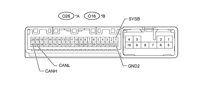
Text in Illustration *A for LHD *B for RHD
-
Disconnect the O26*1 or O16*2 position control ECU assembly connector.
-
*1: for LHD
-
*2: for RHD
-
-
Measure the resistance according to the value(s) in the table below.
for LHD Terminal No. (Symbol) Wiring Color Switch Condition Specified Condition O26-40 (CANH) - O26-39 (CANL) SB - W Ignition switch off 54 to 69 Ω O26-40 (CANH) - O26-21 (GND2) SB- BR Ignition switch off 200 Ω or higher O26-39 (CANL) - O26-21 (GND2) W - BR Ignition switch off 200 Ω or higher O26-40 (CANH) - O26-1 (SYSB) SB - R Ignition switch off 6 kΩ or higher O26-39 (CANL) - O26-1 (SYSB) W - R Ignition switch off 6 kΩ or higher for RHD Terminal No. (Symbol) Wiring Color Switch Condition Specified Condition O16-40 (CANH) - O16-39 (CANL) SB - W Ignition switch off 54 to 69 Ω O16-40 (CANH) - O16-21 (GND2) SB- BR Ignition switch off 200 Ω or higher O16-39 (CANL) - O16-21 (GND2) W - BR Ignition switch off 200 Ω or higher O16-40 (CANH) - O16-1 (SYSB) SB - R Ignition switch off 6 kΩ or higher O16-39 (CANL) - O16-1 (SYSB) W - R Ignition switch off 6 kΩ or higher
-
-
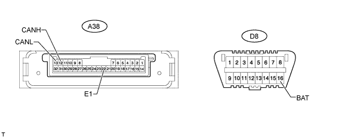
CHECK HEADLIGHT SWIVEL ECU ASSEMBLY (AFS ECU) (w/ Adaptive Front-lighting System)
-
Disconnect the A38 headlight swivel ECU assembly (AFS ECU) connector.
-
Measure the resistance according to the value(s) in the table below.
Terminal No. (Symbol) Wiring Color Switch Condition Specified Condition A38-12 (CANH) - A38-13 (CANL) Y - W Ignition switch off 54 to 69 Ω A38-12 (CANH) - A38-22 (E1) Y - W-B Ignition switch off 200 Ω or higher A38-13 (CANL) - A38-22 (E1) W - W-B Ignition switch off 200 Ω or higher A38-12 (CANH) - D8-16 (BAT) Y - G Ignition switch off 6 kΩ or higher A38-13 (CANL) - D8-16 (BAT) W - G Ignition switch off 6 kΩ or higher
-
-
CHECK DRIVING SUPPORT ECU ASSEMBLY (w/ Dynamic Radar Cruise Control System)
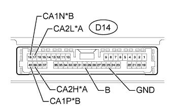
Text in Illustration *A for V2 Bus *B for Parking Assist Bus
-
Disconnect the D14 driving support ECU assembly connector.
-
Measure the resistance according to the value(s) in the table below.
for V2 Bus Terminal No. (Symbol) Wiring Color Switch Condition Specified Condition D14-39 (CA2H) - D14-17 (CA2L) L - W Ignition switch off 54 to 69 Ω D14-39 (CA2H) - D14-25 (GND) L - BR Ignition switch off 200 Ω or higher D14-17 (CA2L) - D14-25 (GND) W - BR Ignition switch off 200 Ω or higher D14-39 (CA2H) - D14-30 (B) L - L Ignition switch off 6 kΩ or higher D14-17 (CA2L) - D14-30 (B) W - L Ignition switch off 6 kΩ or higher for Parking Assist Bus Terminal No. (Symbol) Wiring Color Switch Condition Specified Condition D14-40 (CA1P) - D14-18 (CA1N) R - W Ignition switch off 108 to 132 Ω D14-40 (CA1P) - D14-25 (GND) R - BR Ignition switch off 200 Ω or higher D14-18 (CA1N) - D14-25 (GND) W - BR Ignition switch off 200 Ω or higher D14-40 (CA1P) - D14-30 (B) R - L Ignition switch off 6 kΩ or higher D14-18 (CA1N) - D14-30 (B) W - L Ignition switch off 6 kΩ or higher
-
-
CHECK SEAT BELT CONTROL ECU (w/ Pre-crash Safety System)
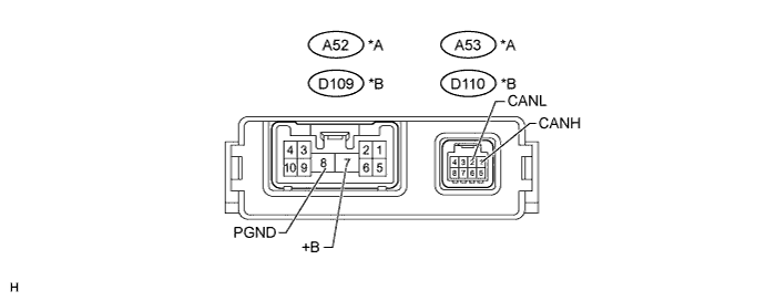
Text in Illustration *A for LHD *B for RHD
-
Disconnect the A52*1 and A53*1 or D109*2 and D110*2 seat belt control ECU connectors.
-
*1: for LHD
-
*2: for RHD
-
-
Measure the resistance according to the value(s) in the table below.
for LHD Terminal No. (Symbol) Wiring Color Switch Condition Specified Condition A53-1 (CANH) - A53-2 (CANL) G - W Ignition switch off 54 to 69 Ω A53-1 (CANH) - A52-8 (PGND) G - W-B Ignition switch off 200 Ω or higher A53-2 (CANL) - A52-8 (PGND) W - W-B Ignition switch off 200 Ω or higher A53-1 (CANH) - A52-7 (+B) G - B Ignition switch off 6 kΩ or higher A53-2 (CANL) - A52-7 (+B) W - B Ignition switch off 6 kΩ or higher for RHD Terminal No. (Symbol) Wiring Color Switch Condition Specified Condition D110-1 (CANH) - D110-2 (CANL) G - W Ignition switch off 54 to 69 Ω D110-1 (CANH) - D109-8 (PGND) G - W-B Ignition switch off 200 Ω or higher D110-2 (CANL) - D109-8 (PGND) W - W-B Ignition switch off 200 Ω or higher D110-1 (CANH) - D109-7 (+B) G - B Ignition switch off 6 kΩ or higher D110-2 (CANL) - D109-7 (+B) W - B Ignition switch off 6 kΩ or higher
-
-
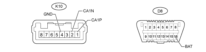
CHECK LANE RECOGNITION CAMERA SENSOR ASSEMBLY (w/ Lane-keeping Assist System)
-
Disconnect the K10 lane recognition camera sensor assembly connector.
-
Measure the resistance according to the value(s) in the table below.
Terminal No. (Symbol) Wiring Color Switch Condition Specified Condition K10-1 (CA1P) - K10-2 (CA1N) LG - W Ignition switch off 54 to 69 Ω K10-1 (CA1P) - K10-4 (GND) LG - BR Ignition switch off 200 Ω or higher K10-2 (CA1N) - K10-4 (GND) W - BR Ignition switch off 200 Ω or higher K10-1 (CA1P) - D8-16 (BAT) LG - G Ignition switch off 6 kΩ or higher K10-2 (CA1N) - D8-16 (BAT) W - G Ignition switch off 6 kΩ or higher
-
-
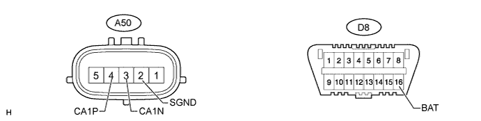
CHECK MILLIMETER WAVE RADAR SENSOR ASSEMBLY (w/ Dynamic Radar Cruise Control System)
-
Disconnect the A50 millimeter wave radar sensor assembly connector.
-
Measure the resistance according to the value(s) in the table below.
Terminal No. (Symbol) Wiring Color Switch Condition Specified Condition A50-4 (CA1P) - A50-3 (CA1N) B - W Ignition switch off 108 to 132 Ω A50-4 (CA1P) - A50-2 (SGND) B - BR Ignition switch off 200 Ω or higher A50-3 (CA1N) - A50-2 (SGND) W - BR Ignition switch off 200 Ω or higher A50-4 (CA1P) - D8-16 (BAT) B - G Ignition switch off 6 kΩ or higher A50-3 (CA1N) - D8-16 (BAT) W - G Ignition switch off 6 kΩ or higher
-