CAN COMMUNICATION SYSTEM SYSTEM DIAGRAM

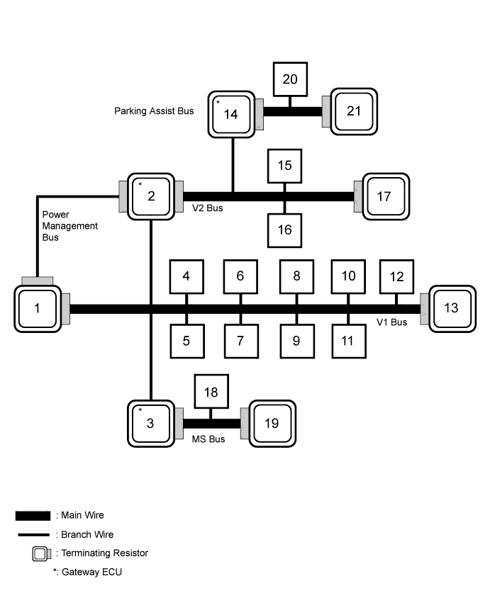
| No. | ECU/Sensor Name |
|---|---|
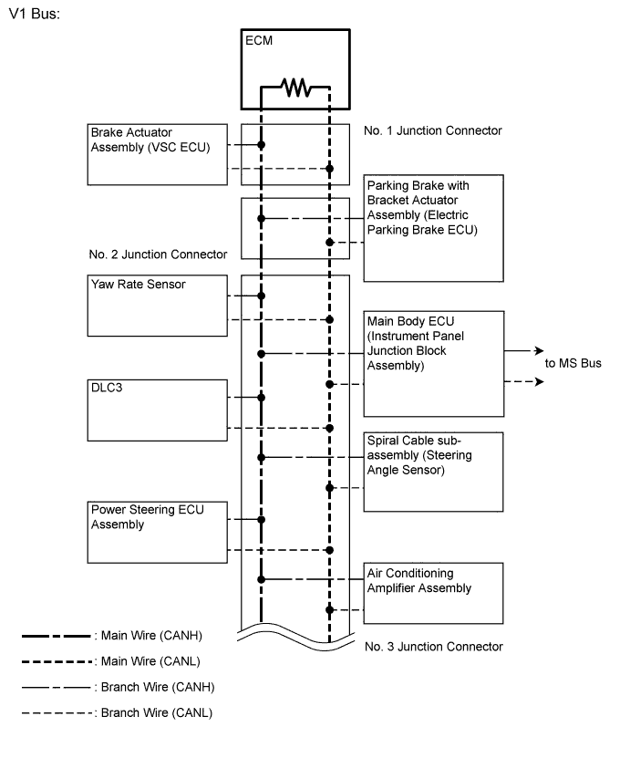
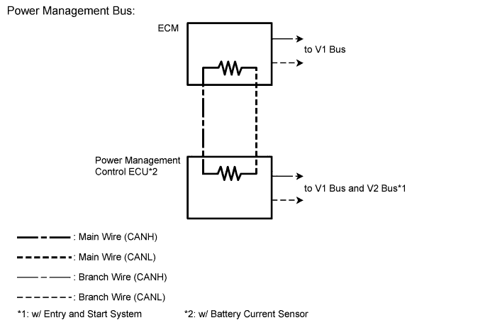
| 1 | ECM |
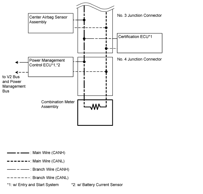
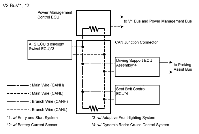
| 2 | Power management control ECU*1 |
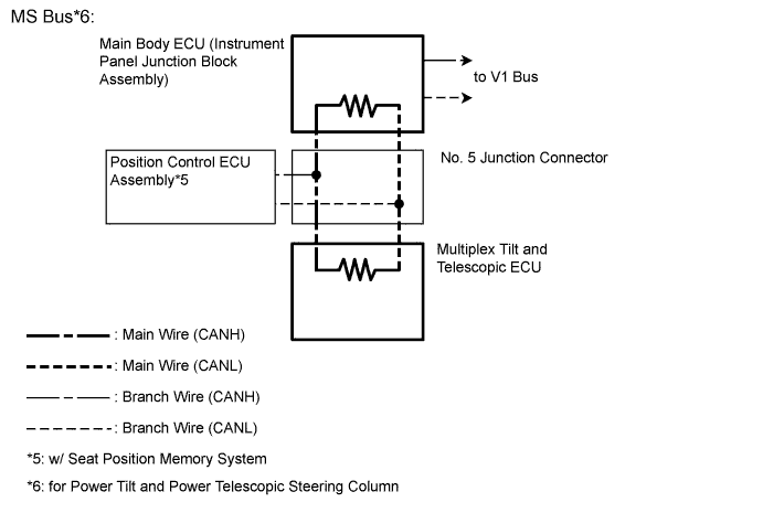
| 3 | Main body ECU (instrument panel junction block assembly) |
| 4 | Brake actuator assembly (VSC ECU) |
| 5 | Parking brake with bracket actuator assembly (electric parking brake ECU) |
| 6 | Yaw rate sensor |
| 7 | DLC3 |
| 8 | Spiral cable sub-assembly (steering angle sensor) |
| 9 | Power steering ECU assembly |
| 10 | Air conditioning amplifier assembly |
| 11 | Certification ECU*2 |
| 12 | Center airbag sensor assembly |
| 13 | Combination meter assembly |
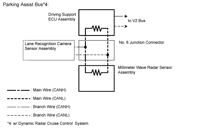
| 14 | Driving Support ECU Assembly*3 |
| 15 | Headlight swivel ECU assembly (AFS ECU)*4 |
| 16 | Seat belt control ECU*3 |
| 17 | CAN junction connector |
| 18 | Position control ECU assembly*5 |
| 19 | Multiplex tilt and telescopic ECU*6 |
| 20 | Lane recognition camera sensor assembly*3 |
| 21 | Millimeter wave radar sensor assembly*3 |
-
*1: w/ Battery Current Sensor
-
*2: w/ Entry and Start System
-
*3: w/ Dynamic Radar Cruise Control System
-
*4: w/ Adaptive Front-lighting System
-
*5: w/ Seat Position Memory System
-
*6: for Power Tilt and Power Telescopic Steering Column
Tech Tips
-
The brake actuator assembly (VSC ECU) stores spiral cable sub-assembly (steering angle sensor) and yaw rate sensor DTCs and performs DTC communication by receiving information from the spiral cable sub-assembly (steering angle sensor) and yaw rate sensor.
-
The ECM uses the CAN communication system to perform DTC communication instead of the conventional communication line (SIL).