CHARGING SYSTEM, Diagnostic DTC:P1550, P1551, P1552

| DTC Code | DTC Name |
|---|---|
| P1550 | Battery Current Sensor Circuit |
| P1551 | Battery Current Sensor Circuit Low |
| P1552 | Battery Current Sensor Circuit High |
DESCRIPTION
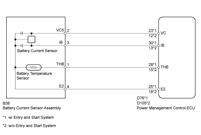
The battery current sensor assembly detects the battery charge and discharge current amount. The battery current sensor assembly changes this information into a voltage signal and outputs it to the power management control ECU. Based on this signal, the power management control ECU sends power generation voltage commands to the generator.
| DTC Code | DTC Detection Condition | Trouble Area |
|---|---|---|
| P1550 | When the ignition switch is ON, the difference between the maximum and minimum current values is 1 A or less for 10 seconds or more (1 trip detection logic). |
|
| P1551 | When the ignition switch is ON, the battery current sensor output is 0.2 V or less for 0.5 seconds or more (1 trip detection logic). |
|
| P1552 | When the ignition switch is ON, the battery current sensor output is 4.8 V or higher for 0.5 seconds or more (1 trip detection logic). |
|
WIRING DIAGRAM
INSPECTION PROCEDURE
PROCEDURE
-
CHECK FOR DTC
-
Connect the intelligent tester to the DLC3.
-
Turn the ignition switch to ON.
-
Turn the tester on.
-
According to the display on the tester, check for DTCs Click here.
Result Result Proceed to DTC P1550, P1551 or P1552 is output. A DTCs other than P1550, P1551 and P1552 are output. B
B 
GO TO DIAGNOSTIC TROUBLE CODE CHART Click here
A 
-
-
READ VALUE USING INTELLIGENT TESTER (BATTERY CURRENT)
-
Connect the intelligent tester to the DLC3.
-
Turn the ignition switch to ON and turn off all electrical devices (headlights, blower motor, wiper, rear defogger, etc.).
-
Turn the tester on.
-
Select the item below in the Data List, and read the display on the intelligent tester Click here.
Charging Control Tester Display Measurement Item/Range Normal Condition Diagnostic Note Battery Current Battery current / -125 to 124.9 A Changes in response to generator power generation amount after engine warmed up while vehicle driven - Result Result Proceed to Current value displayed on tester is fixed at 0 A and does not change, or only changes by 1 A or less between -98 and 98 A. A Current value displayed on tester changes between -20 and 0 A. B
B
USE SIMULATION METHOD TO CHECK Click here
A
-
-
CHECK BATTERY CURRENT SENSOR ASSEMBLY
-
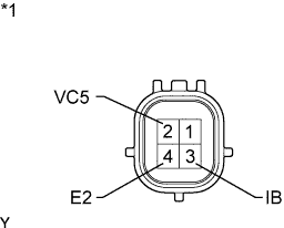
Text in Illustration *1 Component without harness connected
(Battery Current Sensor)
Disconnect the B38 battery current sensor connector.
-
Measure the resistance according to the value(s) in the table below.
Standard Resistance Tester Connection Condition Specified Condition 2 (VC5) - 4 (E2) Always 3 to 10 kΩ 2 (VC5) - 3 (IB) Always Below 0.5 kΩ 3 (IB) - 4 (E2) Always 3 to 10 kΩ Result Result Proceed to OK w/ Entry and Start System A w/o Entry and Start System B NG C
B 
CHECK HARNESS AND CONNECTOR (POWER MANAGEMENT CONTROL ECU - BATTERY CURRENT SENSOR) Click here
C
REPLACE BATTERY CURRENT SENSOR ASSEMBLY Click here
A
-
-
CHECK HARNESS AND CONNECTOR (POWER MANAGEMENT CONTROL ECU - BATTERY CURRENT SENSOR)
w/ Entry and Start System:
-
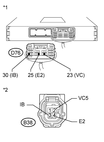
Text in Illustration *1 Rear view of wire harness connector
(to Power Management Control ECU)
*2 Front view of wire harness connector
(to Battery Current Sensor)
Disconnect the D76 power management control ECU connector.
-
Disconnect the B38 battery current sensor connector.
-
Measure the resistance according to the value(s) in the table below.
Standard Resistance Tester Connection Condition Specified Condition D76-23 (VC) - B38-2 (VC5) Always Below 1 Ω D76-25 (E2) - B38-4 (E2) D76-30 (IB) - B38-3 (IB) D76-23 (VC) - Body ground Always 10 kΩ or higher D76-25 (E2) - Body ground D76-30 (IB) - Body ground
NG
REPAIR OR REPLACE HARNESS OR CONNECTOR (POWER MANAGEMENT CONTROL ECU - BATTERY CURRENT SENSOR)
OK 
REPLACE POWER MANAGEMENT CONTROL ECU Click here
-
-
CHECK HARNESS AND CONNECTOR (POWER MANAGEMENT CONTROL ECU - BATTERY CURRENT SENSOR)
w/o Entry and Start System:
-
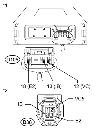
Text in Illustration *1 Rear view of wire harness connector
(to Power Management Control ECU)
*2 Front view of wire harness connector
(to Battery Current Sensor)
Disconnect the D105 power management control ECU connector.
-
Disconnect the B38 battery current sensor connector.
-
Measure the resistance according to the value(s) in the table below.
Standard Resistance Tester Connection Condition Specified Condition D105-12 (VC) - B38-2 (VC5) Always Below 1 Ω D105-18 (E2) - B38-4 (E2) D105-13 (IB) - B38-3 (IB) D105-12 (VC) - Body ground Always 10 kΩ or higher D105-18 (E2) - Body ground D105-13 (IB) - Body ground
NG
REPAIR OR REPLACE HARNESS OR CONNECTOR (POWER MANAGEMENT CONTROL ECU - BATTERY CURRENT SENSOR)
OK
REPLACE POWER MANAGEMENT CONTROL ECU Click here
-