CHARGING SYSTEM TERMINALS OF ECU

-
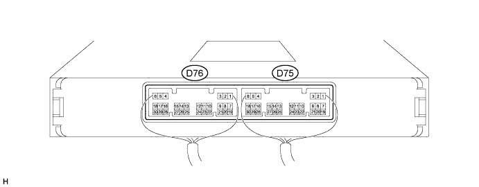
CHECK POWER MANAGEMENT CONTROL ECU (w/ Entry and Start System)
-
Measure the voltage and resistance according to the value(s) in the table below.
Tech Tips
Perform the measurements with the connectors connected.
Terminal No. (Symbol) Wiring Color Terminal Description Condition Specified Condition D75-1 (AM22) - Body ground W Battery Always 9.5 to 16 V D75-2 (AM21) - Body ground W Battery Always 9.5 to 16 V D76-10 (RLO) - D76-25 (E2) V - BR Generator signal Engine warmed up, charging control operating, vehicle driven at constant speed Pulse generation
(See waveform 1)
Engine warmed up, charging control operating, vehicle accelerating Pulse generation
(See waveform 2)
Engine warmed up, charging control operating, vehicle decelerating Pulse generation
(See waveform 3)
D76-23 (VC) - D76-25 (E2) LG - BR Battery current sensor power supply Ignition switch ON 4.5 to 5.5 V D76-28 (THB) - D76-25 (E2) P - BR Battery current sensor thermistor signal Ignition switch ON 0.2 to 4.8 V D76-30 (IB) - D76-25 (E2) B - BR Battery current sensor signal Ignition switch ON
(Temperature of thermistor of battery current sensor: -30 to 90°C (-86 to 194°F))
0.2 to 4.8 V D76-25 (E2) - Body ground BR Battery current sensor ground Always Below 1 Ω If the result is not as specified, the ECU may have a malfunction.
-
Using an oscilloscope, check the signal waveform of the ECU.
Tech Tips
The oscilloscope waveform shown in the illustration is an example for reference only. Waveforms with noise or chattering are not shown.
-
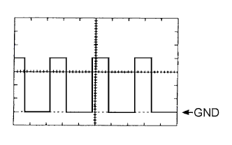
Waveform 1
Tech Tips
As the duty cycle changes in accordance with the electrical load and battery condition, the output waveform also changes.
-
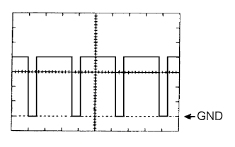
Waveform 2
Tech Tips
As the duty cycle changes in accordance with the electrical load and battery condition, the output waveform also changes.
-
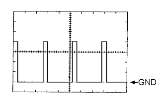
Waveform 3
Tech Tips
As the duty cycle changes in accordance with the electrical load and battery condition, the output waveform also changes.
-
-
-
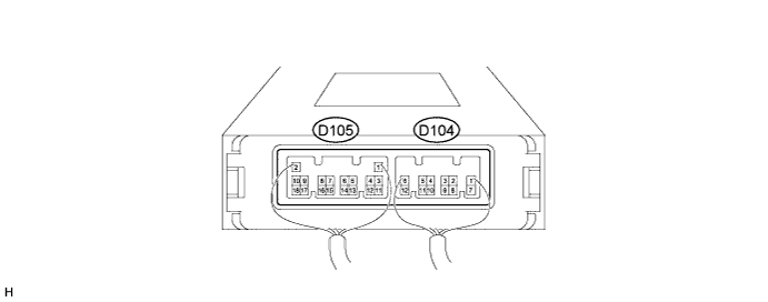
CHECK POWER MANAGEMENT CONTROL ECU (w/o Entry and Start System)
-
Measure the voltage and resistance according to the value(s) in the table below.
Tech Tips
Perform the measurements with the connectors connected.
Terminal No. (Symbol) Wiring Color Terminal Description Condition Specified Condition D104-8 (AM21) - Body ground W Battery Always 9.5 to 16 V D105-14 (RLO) - D105-18 (E2) V - BR Generator signal Engine warmed up, charging control operating, vehicle driven at constant speed Pulse generation
(See waveform 1)
Engine warmed up, charging control operating, vehicle accelerating Pulse generation
(See waveform 2)
Engine warmed up, charging control operating, vehicle decelerating Pulse generation
(See waveform 3)
D105-12 (VC) - D105-18 (E2) LG - BR Battery current sensor power supply Ignition switch ON 4.5 to 5.5 V D105-15 (THB) - D105-18 (E2) P - BR Battery current sensor thermistor signal Ignition switch ON 0.2 to 4.8 V D105-13 (IB) - D105-18 (E2) B - BR Battery current sensor signal Ignition switch ON
(Temperature of thermistor of battery current sensor: -30 to 90°C (-86 to 194°F))
0.2 to 4.8 V D105-18 (E2) - Body ground BR Battery current sensor ground Always Below 1 Ω If the result is not as specified, the ECU may have a malfunction.
-
Using an oscilloscope, check the signal waveform of the ECU.
Tech Tips
The oscilloscope waveform shown in the illustration is an example for reference only. Waveforms with noise or chattering are not shown.
-
Waveform 1
Tech Tips
As the duty cycle changes in accordance with the electrical load and battery condition, the output waveform also changes.
-
Waveform 2
Tech Tips
As the duty cycle changes in accordance with the electrical load and battery condition, the output waveform also changes.
-
Waveform 3
Tech Tips
As the duty cycle changes in accordance with the electrical load and battery condition, the output waveform also changes.
-
-