TOYOTA PARKING ASSIST-SENSOR SYSTEM Clearance Warning ECU Power Source Circuit
DESCRIPTION
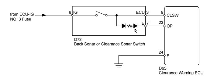
This circuit is the power source circuit to operate the clearance warning ECU.
WIRING DIAGRAM
INSPECTION PROCEDURE
Note
Inspect the fuses for circuits related to this system before performing the following inspection procedure.
PROCEDURE
-
CHECK HARNESS AND CONNECTOR (BACK SONAR OR CLEARANCE SONAR SWITCH - BATTERY)
-
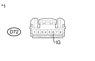
Text in Illustration *1 Front view of wire harness connector
(to Back Sonar or Clearance Sonar Switch)
Disconnect the D72 switch connector.
-
Measure the voltage according to the value(s) in the table below.
Standard Voltage Tester Connection Switch Condition Specified Condition D72-6 (IG) - Body ground Ignition switch ON 11 to 14 V D72-6 (IG) - Body ground Ignition switch off Below 1 V
NG 
REPAIR OR REPLACE HARNESS OR CONNECTOR
OK 
-
-
INSPECT BACK SONAR OR CLEARANCE SONAR SWITCH
-
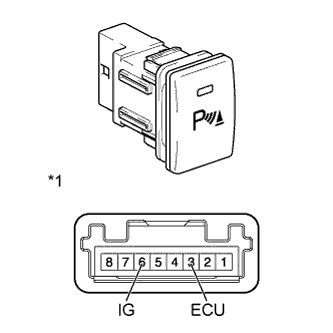
Text in Illustration *1 Component without harness connected
(Back Sonar or Clearance Sonar Switch)
Remove the back sonar or clearance sonar switch.
Refer to the following procedures for LHD Click here
Refer to the following procedures for RHD Click here
-
Measure the resistance according to the value(s) in the table below.
Standard Resistance Tester Connection Switch Condition Specified Condition 6 (IG) - 3 (ECU) Pressed (on) Below 1 Ω 6 (IG) - 3 (ECU) Not pressed (off) 10 kΩ or higher Result Result Proceed to OK A NG (for LHD) B NG (for RHD) C
B
REPLACE BACK SONAR OR CLEARANCE SONAR SWITCH Click here
C
REPLACE BACK SONAR OR CLEARANCE SONAR SWITCH Click here
A
-
-
CHECK HARNESS AND CONNECTOR (BACK SONAR OR CLEARANCE SONAR SWITCH - CLEARANCE WARNING ECU)
-
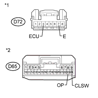
Text in Illustration *1 Front view of wire harness connector
(to Back Sonar or Clearance Sonar Switch)
*2 Front view of wire harness connector
(to Clearance Warning ECU)
Disconnect the D72 switch connector.
-
Disconnect the D65 ECU connector.
-
Measure the resistance according to the value(s) in the table below.
Standard Resistance Tester Connection Condition Specified Condition D72-3 (ECU) - D65-9 (CLSW) Always Below 1 Ω D72-7 (E) - D65-23 (OP) Always Below 1 Ω D72-3 (ECU) - Body ground Always 10 kΩ or higher D72-7 (E) - Body ground Always 10 kΩ or higher
NG
REPAIR OR REPLACE HARNESS OR CONNECTOR
OK 
PROCEED TO NEXT SUSPECTED AREA SHOWN IN PROBLEM SYMPTOMS TABLE Click here
-