TOYOTA PARKING ASSIST-SENSOR SYSTEM Clearance Warning Buzzer Circuit
DESCRIPTION
The clearance warning buzzer sounds to alert the driver and the buzzed frequency changes depending on the distance to an obstacle.
WIRING DIAGRAM
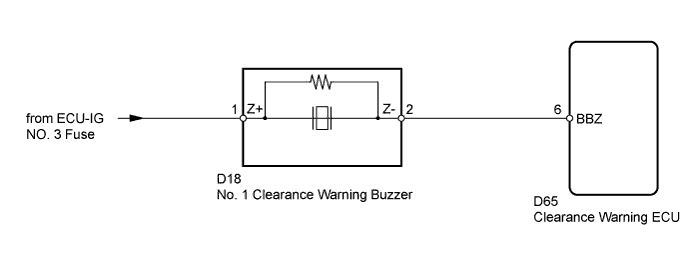
INSPECTION PROCEDURE
Note
Inspect the fuses for circuits related to this system before performing the following inspection procedure.
PROCEDURE
-
CHECK HARNESS AND CONNECTOR (NO. 1 CLEARANCE WARNING BUZZER - BATTERY)
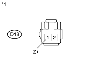
Text in Illustration *1 Front view of wire harness connector
(to No. 1 Clearance Warning Buzzer)
-
Disconnect the D18 buzzer connector.
-
Measure the voltage according to the value(s) in the table below.
Standard Voltage Tester Connection Switch Condition Specified Condition D18-1 (Z+) - Body ground Ignition switch ON 11 to 14 V D18-1 (Z+) - Body ground Ignition switch off Below 1 V
NG 
REPAIR OR REPLACE HARNESS OR CONNECTOR
OK 
-
-
CHECK HARNESS AND CONNECTOR (NO. 1 CLEARANCE WARNING BUZZER - CLEARANCE WARNING ECU)
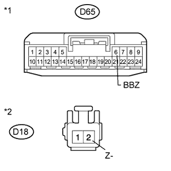
Text in Illustration *1 Front view of wire harness connector
(to Clearance Warning ECU)
*2 Front view of wire harness connector
(to No. 1 Clearance Warning Buzzer)
-
Disconnect the D65 ECU connector.
-
Disconnect the D18 buzzer connector.
-
Measure the resistance according to the value(s) in the table below.
Standard Resistance Tester Connection Condition Specified Condition D65-6 (BBZ) - D18-2 (Z-) Always Below 1 Ω D65-6 (BBZ) - Body ground Always 10 kΩ or higher
NG
REPAIR OR REPLACE HARNESS OR CONNECTOR
OK
-
-
REPLACE NO. 1 CLEARANCE WARNING BUZZER
-
Replace the No. 1 clearance warning buzzer with a normally functioning or new one Click here.
NEXT
-
-
CHECK NO. 1 CLEARANCE WARNING BUZZER
-
Check that the No. 1 clearance warning buzzer operates normally.
OK No. 1 clearance warning buzzer operates normally.
NG
PROCEED TO NEXT SUSPECTED AREA SHOWN IN PROBLEM SYMPTOMS TABLE Click here
OK 
END
-