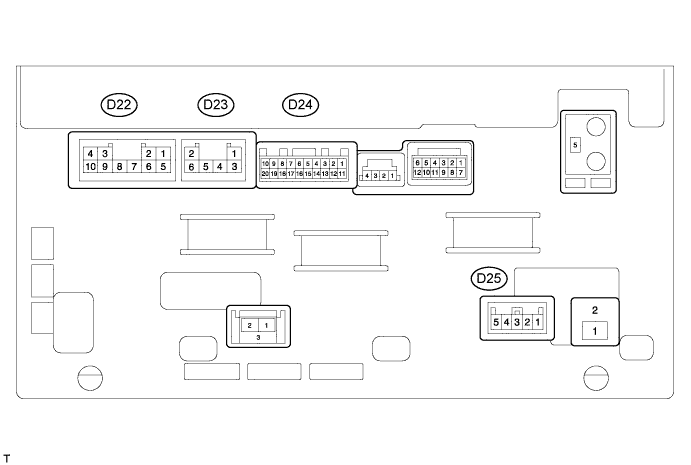
NAVIGATION SYSTEM (for HDD) TERMINALS OF ECU

-
CHECK NAVIGATION RECEIVER ASSEMBLY
-
Disconnect the D22 navigation receiver connector.
-
Measure the resistance and voltage according to the value(s) in the table below.
Terminal No. (Symbol) Wiring Color Terminal Description Condition Specified Condition D22-3 (ACC) - D22-7 (GND) GR - BR Accessory (On) Ignition switch off Below 1 V D22-3 (ACC) - D22-7 (GND) GR - BR Accessory (On) Ignition switch ACC 11 to 14 V D22-4 (B) - D22-7 (GND) SB - BR Battery Always 11 to 14 V D22-7 (GND) - Body ground BR - Body ground Ground Always Below 1 Ω
-
If the result is not as specified, there may be a malfunction on the wire harness side.
-
-
Reconnect the D22 navigation receiver connector.
-
Measure the resistance and voltage according to the value(s) in the table below.
Terminal No. (Symbol) Wiring Color Terminal Description Condition Specified Condition D22-1 (FR+) - D22-7 (GND) LG - BR Sound signal (Front Right) Audio system playing A waveform synchronized with the sound is output D22-2 (FL+) - D22-7 (GND) P - BR Sound signal (Front Left) Audio system playing A waveform synchronized with the sound is output D22-5 (FR-) - D22-7 (GND) L - BR Sound signal (Front Right) Audio system playing A waveform synchronized with the sound is output D22-6 (FL-) - D22-7 (GND) V - BR Sound signal (Front Left) Audio system playing A waveform synchronized with the sound is output D22-9 (AMP) - D22-7 (GND) BR - BR Power source of stereo component amplifier Audio system playing 11 to 14 V D22-10 (ILL+) - D22-7 (GND) G - BR Illumination signal Light control switch off Below 1 V Light control switch on 11 to 14 V D23-1 (RR+) - D22-7 (GND) R - BR Sound signal (Rear Right) Audio system playing A waveform synchronized with the sound is output D23-2 (RL+) - D22-7 (GND) B - BR Sound signal (Rear Left) Audio system playing A waveform synchronized with the sound is output D23-3 (RR-) - D22-7 (GND) W - BR Sound signal (Rear Right) Audio system playing A waveform synchronized with the sound is output D23-6 (RL-) - D22-7 (GND) Y - BR Sound signal (Rear Left) Audio system playing A waveform synchronized with the sound is output D24-1 (V+) - D24-11 (V-) R - W Display signal Ignition switch ON, shift lever in R Pulse generation (Refer to waveform 1) Ignition switch ON, shift lever in R, screen blacked out by covering camera lens Pulse generation (Refer to waveform 2) D24-2 (CA+) - D22-7 (GND) B - BR Television camera power supply Ignition switch ON, shift lever in R 5.8 to 6.2 V D24-3 (SNS2) - D22-7 (GND) L- BR Microphone connection detection signal Always Below 1 Ω D24-4 (MIN+) - D22-7 (GND) W - BR Microphone voice signal See "Microphone & Voice Recognition Check" Click here
- D24-5 (MACC) - D22-7 (GND) B - BR Microphone amplifier power supply Ignition switch off Below 1 V Ignition switch ACC 4.75 to 5.25 V D24-6 (SWG) - Body ground V - Body ground Steering pad switch ground Always Below 1 V D24-7 (SW1) - D24-6 (SWG) P - V Steering pad switch signal No switch is pushed
→ SEEK+ switch pushed
→ SEEK- switch pushed
→ VOL+ switch pushed
→ VOL- switch pushed
2.97 to 3.56 V
→ 0.27 to 0.35 V
→ 0.86 to 1.03 V
→ 1.51 to 1.79 V
→ 2.22 to 2.66 V
D24-8 (SW2) - D24-6 (SWG) SB - V Steering pad switch signal No switch is pushed
→ MODE switch pushed
→ On Hook switch pushed
→ Off Hook switch pushed
→ Voice switch pushed
2.97 to 3.56 V
→ 0.27 to 0.35 V
→ 0.86 to 1.03 V
→ 1.51 to 1.79 V
→ 2.22 to 2.66 V
D24-11 (V-) - D24-12 (CGND) W - Shielded Ground Always Below 1 V D24-12 (CGND) - Body ground Shielded - Body ground Ground Always Below 1 V D24-13 (MIN-) - D22-7 (GND) R - BR Microphone voice signal See "Microphone&Voice Recognition Check" Click here
- D24-14 (SGND) - D22-7 (GND) Shielded - BR Signal ground Always Below 1 V D24-15 (ARI) - D22-7 (GND) R - BR Sound signal (Right) External device playing (when stereo jack is used) A waveform synchronized with the sound is input D24-16 (ASGN) - D22-7 (GND) W - BR Ground Always Below 1 V D24-17 (ALI) - D22-7 (GND) B - BR Sound signal (Left) External device playing (when stereo jack is used) A waveform synchronized with the sound is input D24-18 (AGND) - Body ground Shielded - Body ground Shielded ground Always Below 1 V D24-19 (AUXI) - D22-7 (GND) L - BR External device connection detection signal External device connected 1.1 to 1.5 V External device is not connected 2.0 to 2.4 V D24-20 (LRHD)* - Body ground W-B - Body ground Ground Always Below 1 V D25-3 (SPD) - D22-7 (GND) Y - BR Speed signal from combination meter See "Vehicle Signal Check Mode" Click here
- D25-5 (REV) - D22-7 (GND) R - BR Reverse signal See "Vehicle Signal Check Mode" Click here
- *: for RHD
-
If the result is not as specified, the navigation receiver assembly may have a malfunction.
-
-
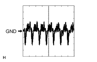
Using an oscilloscope, check waveform 1.
Measurement Condition Item Content Terminal No. (Symbol) D24-1 (V+) - D24-11 (V-) Tool Setting 0.2 V/DIV., 50 μs/DIV. Condition Ignition switch ON, shift lever in R -
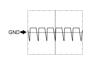
Using an oscilloscope, check waveform 2.
Measurement Condition Item Content Terminal No. (Symbol) D24-1 (V+) - D24-11 (V-) Tool Setting 0.2 V/DIV., 50 μs/DIV. Condition Ignition switch ON, shift lever in R, screen blacked out by covering camera lens
-