NAVIGATION SYSTEM (for DVD) Reverse Signal Circuit
DESCRIPTION
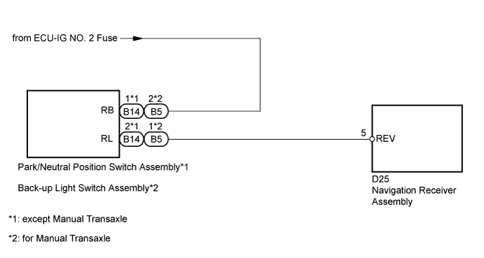
The navigation receiver assembly receives a reverse signal from the park/neutral position switch assembly*1 or back-up light switch assembly*2 and information about the GPS antenna, and then adjusts the vehicle position.
-
*1: except Manual Transaxle
-
*2: for Manual Transaxle
WIRING DIAGRAM
INSPECTION PROCEDURE
Note
Inspect the fuses for circuits related to this system before performing the following inspection procedure.
PROCEDURE
-
CHECK NAVIGATION RECEIVER ASSEMBLY (DISPLAY CHECK MODE)
-
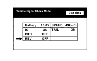
Enter the "Display Check" mode and select "Vehicle Signal Check Mode" Click here.
-
Check that the display changes between ON and OFF according to the shift lever operation.
OK Shift Lever Position Display R ON Except R OFF Tech Tips
This display is updated once per second. As a result, it is normal for the display to lag behind the actual shift lever operation.
NG 
CHECK NAVIGATION RECEIVER ASSEMBLY (REVERSE SIGNAL) Click here
OK 
PROCEED TO NEXT SUSPECTED AREA SHOWN IN PROBLEM SYMPTOMS TABLE Click here
-
-
CHECK NAVIGATION RECEIVER ASSEMBLY (REVERSE SIGNAL)
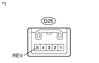
Text in Illustration *1 Component with harness connected
(Navigation Receiver Assembly)
-
Measure the voltage according to the value(s) in the table below.
Standard Voltage Tester Connection Switch Condition Specified Condition D25-5 (REV) - Body ground Ignition switch ON
Shift lever in R
11 to 14 V D25-5 (REV) - Body ground Ignition switch ON
Shift lever in any position except R
Below 1 V
NG
CHECK TRANSAXLE TYPE Click here
OK
REPLACE NAVIGATION RECEIVER ASSEMBLY Click here
-
-
CHECK TRANSAXLE TYPE
-
Check the transaxle type.
Result Result Proceed to Manual Transaxle A except Manual Transaxle B
B
CHECK HARNESS AND CONNECTOR (NAVIGATION RECEIVER ASSEMBLY - PARK/NEUTRAL POSITION SWITCH) Click here
A 
-
-
CHECK HARNESS AND CONNECTOR (NAVIGATION RECEIVER - BACK-UP LIGHT SWITCH)
-
Disconnect the D25 navigation receiver assembly connector.
-
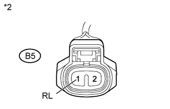
Disconnect the B5 back-up light switch assembly connector.
-
Measure the resistance according to the value(s) in the table below.
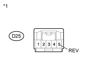
Standard Resistance Tester Connection Condition Specified Condition D25-5 (REV) - B5-1 (RL) Always Below 1 Ω D25-5 (REV) - Body ground Always 10 kΩ or higher Text in Illustration *1 Front view of wire harness connector
(to Navigation Receiver Assembly)
*2 Front view of wire harness connector
(to Back-up Light Switch Assembly)
NG 
REPAIR OR REPLACE HARNESS OR CONNECTOR
OK
-
-
INSPECT BACK-UP LIGHT SWITCH ASSEMBLY
-
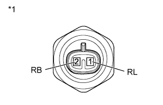
Text in Illustration *1 Component without harness connected
(Back-up Light Switch Assembly)
Disconnect the B5 switch connector.
-
Measure the resistance according to the value(s) in the table below.
Standard Resistance Tester Connection Condition Specified Condition 1 (RL) - 2 (RB) Shift lever in R Below 1 Ω 1 (RL) - 2 (RB) Shift lever not in R 10 kΩ or higher Result Result Proceed to OK A NG (for EA63) B NG (for EA65) C
B
REPLACE BACK-UP LIGHT SWITCH ASSEMBLY Click here
C
REPLACE BACK-UP LIGHT SWITCH ASSEMBLY Click here
A
PROCEED TO NEXT SUSPECTED AREA SHOWN IN PROBLEM SYMPTOMS TABLE Click here
-
-
CHECK HARNESS AND CONNECTOR (NAVIGATION RECEIVER ASSEMBLY - PARK/NEUTRAL POSITION SWITCH)
-
Disconnect the D25 navigation receiver assembly connector.
-
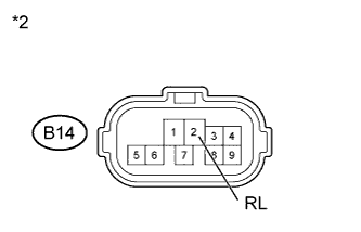
Disconnect the B14 park/neutral position switch assembly connector.
-
Measure the resistance according to the value(s) in the table below.
Standard Resistance Tester Connection Condition Specified Condition D25-5 (REV) - B14-2 (RL) Always Below 1 Ω D25-5 (REV) - Body ground Always 10 kΩ or higher Text in Illustration *1 Front view of wire harness connector
(to Navigation Receiver Assembly)
*2 Front view of wire harness connector
(to Park/Neutral Position Switch Assembly)
NG
REPAIR OR REPLACE HARNESS OR CONNECTOR
OK
-
-
INSPECT PARK/NEUTRAL POSITION SWITCH ASSEMBLY
-
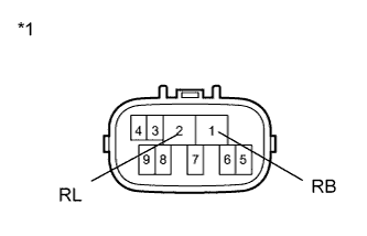
Text in Illustration *1 Component without harness connected
(Park/Neutral Position Switch Assembly)
Disconnect the B14 switch connector.
-
Measure the resistance according to the value(s) in the table below.
Standard Resistance Tester Connection Condition Specified Condition 1 (RB) - 2 (RL) Shift lever in R Below 1 Ω 1 (RB) - 2 (RL) Shift lever not in P 10 kΩ or higher
NG
REPLACE PARK/NEUTRAL POSITION SWITCH ASSEMBLY Click here
OK
PROCEED TO NEXT SUSPECTED AREA SHOWN IN PROBLEM SYMPTOMS TABLE Click here
-