NAVIGATION SYSTEM Vehicle Speed Signal Circuit between Radio Receiver and Extension Module
DESCRIPTION
The extension module receives a vehicle speed signal from the radio and display receiver assembly and information from the navigation antenna, and then adjusts vehicle position.
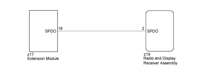
WIRING DIAGRAM
INSPECTION PROCEDURE
PROCEDURE
-
CHECK HARNESS AND CONNECTOR (RADIO AND DISPLAY RECEIVER ASSEMBLY - EXTENSION MODULE)
-
Disconnect the z19 radio and display receiver assembly connector.
-
Disconnect the z17 extension module connector.
-
Measure the resistance according to the value(s) in the table below.
Standard Resistance Tester Connection Condition Specified Condition z19-2 (SPDO) - z17-18 (SPDO) Always Below 1 Ω z19-2 (SPDO) - Body ground Always 10 kΩ or higher
NG 
REPAIR OR REPLACE HARNESS OR CONNECTOR
OK 
PROCEED TO NEXT SUSPECTED AREA SHOWN IN PROBLEM SYMPTOMS TABLE Click here
-