NAVIGATION SYSTEM, Diagnostic DTC:B15C3

| DTC Code | DTC Name |
|---|---|
| B15C3 | Speaker Output Short |
DESCRIPTION
This DTC is stored when a malfunction occurs in the speakers.
| DTC Code | DTC Detection Condition | Trouble Area |
|---|---|---|
| B15C3 | A short is detected in the speaker output circuit. |
|
-
*: for 11 Speakers
WIRING DIAGRAM
-
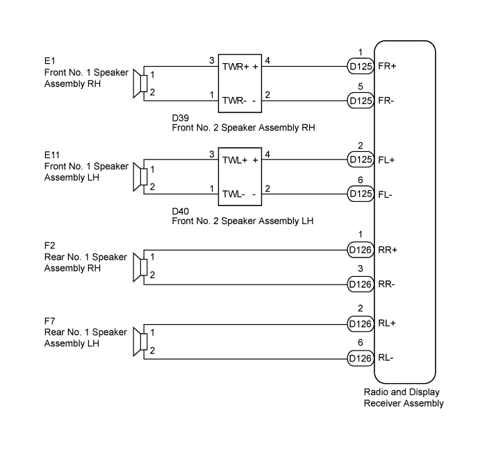
for 6 Speakers
-
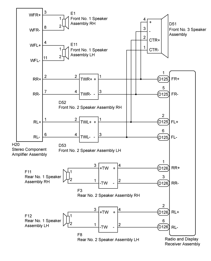
for 11 Speakers
INSPECTION PROCEDURE
PROCEDURE
-
CONFIRM MODEL
Result Result Proceed to for 6 Speakers A for 11 Speakers B
B 
CHECK HARNESS AND CONNECTOR Click here
A 
-
CHECK HARNESS AND CONNECTOR
-
*1: for RH Side
-
*2: for LH Side
-
Disconnect the D125 and D126 radio and display receiver assembly connectors.
-
Disconnect the E1*1 and E11*2 front No. 1 speaker assembly connectors.
-
Disconnect the D39*1 and D40*2 front No. 2 speaker assembly connectors.
-
Disconnect the F2*1 and F7*2 rear No. 1 speaker assembly connectors.
-
Measure the resistance between each of the radio and display receiver assembly and the front No. 2 speaker assembly to check for an open circuit in the wire harness.
Standard Resistance Tester Connection Condition Specified Condition D125-1 (FR+) - D39-4 (+) Always Below 1 Ω D125-5 (FR-) - D39-2 (-) Always Below 1 Ω D125-2 (FL+) - D40-4 (+) Always Below 1 Ω D125-6 (FL-) - D40-2 (-) Always Below 1 Ω -
Measure the resistance between each of the front No. 2 speaker assembly and front No. 1 speaker assembly to check for an open circuit in the wire harness.
Standard Resistance Tester Connection Condition Specified Condition D39-3 (TWR+) - E1-1 Always Below 1 Ω D39-1 (TWR-) - E1-2 Always Below 1 Ω D40-3 (TWL+) - E11-1 Always Below 1 Ω D40-1 (TWL-) - E11-2 Always Below 1 Ω -
Measure the resistance between each of the radio and display receiver assembly and the rear No. 1 speaker assembly to check for an open circuit in the wire harness.
Standard Resistance Tester Connection Condition Specified Condition D126-1 (RR+) - F2-1 Always Below 1 Ω D126-3 (RR-) - F2-2 Always Below 1 Ω D126-2 (RL+) - F7-1 Always Below 1 Ω D126-6 (RL-) - F7-2 Always Below 1 Ω -
Measure the resistance between each speaker assembly and body ground to check for a short circuit in the wire harness.
Standard Resistance Tester Connection Condition Specified Condition E1-1 - Body ground Always 10 kΩ or higher E1-2 - Body ground Always 10 kΩ or higher E11-1 - Body ground Always 10 kΩ or higher E11-2 - Body ground Always 10 kΩ or higher D39-4 (+) - Body ground Always 10 kΩ or higher D39-2 (-) - Body ground Always 10 kΩ or higher D40-4 (+) - Body ground Always 10 kΩ or higher D40-2 (-) - Body ground Always 10 kΩ or higher F2-1 - Body ground Always 10 kΩ or higher F2-2 - Body ground Always 10 kΩ or higher F7-1 - Body ground Always 10 kΩ or higher F7-2 - Body ground Always 10 kΩ or higher
NG 
REPAIR OR REPLACE HARNESS OR CONNECTOR
OK
-
-
INSPECT FRONT NO. 1 SPEAKER ASSEMBLY
-
Disconnect the E1*1 and/or E11*2 front No. 1 speaker assembly connectors.
-
*1: for RH Side
-
*2: for LH Side
-
-
Measure the resistance according to the value(s) in the table below.
Standard Resistance Tester Connection Condition Specified Condition 1 - 2 Always 4 Ω
NG
REPLACE FRONT NO. 1 SPEAKER ASSEMBLY Click here
OK
-
-
INSPECT REAR NO. 1 SPEAKER ASSEMBLY
-
Disconnect the F2*1 and/or F7*2 rear No. 1 speaker assembly connectors.
-
*1: for RH Side
-
*2: for LH Side
-
-
Measure the resistance according to the value(s) in the table below.
Standard Resistance Tester Connection Condition Specified Condition 1 - 2 Always 4 Ω
NG
REPLACE REAR NO. 1 SPEAKER ASSEMBLY Click here
OK
-
-
REPLACE FRONT NO. 2 SPEAKER ASSEMBLY
-
Temporarily replace the front No. 2 speaker assembly with a new or normally functioning one Click here.
-
Check that the speaker sounds normally.
OK Malfunction disappears.
NG
REPLACE RADIO AND DISPLAY RECEIVER ASSEMBLY Click here
OK 
END (FRONT NO. 2 SPEAKER ASSEMBLY IS DEFECTIVE)
-
-
CHECK HARNESS AND CONNECTOR
*1: for RH Side
*2: for LH Side
-
Disconnect the D125 and D126 radio and display receiver assembly connectors.
-
Disconnect the H20 stereo component amplifier assembly connector.
-
Disconnect the E1*1 and E11*2 front No. 1 speaker assembly connectors.
-
Disconnect the D52*1 and D53*2 front No. 2 speaker assembly connectors.
-
Disconnect the F11*1 and F12*2 rear No. 1 speaker assembly connectors.
-
Disconnect the F3*1 and F8*2 rear No. 2 speaker assembly connectors.
-
Disconnect the D51 front No. 3 speaker assembly connector.
-
Measure the resistance between each of the stereo component amplifier assembly and front No. 1 speaker assembly to check for an open circuit in the wire harness.
Standard Resistance Tester Connection Condition Specified Condition H20-3 (WFR+) - E1-1 Always Below 1 Ω H20-8 (WFR-) - E1-2 Always Below 1 Ω H20-4 (WFL+) - E11-1 Always Below 1 Ω H20-11 (WFL-) - E11-2 Always Below 1 Ω -
Measure the resistance between each of the radio and display receiver assembly and the front No. 2 speaker assembly to check for an open circuit in the wire harness.
Standard Resistance Tester Connection Condition Specified Condition D125-1 (FR+) - D52-1 (+) Always Below 1 Ω D125-5 (FR-) - D52-3 (-) Always Below 1 Ω D125-2 (FL+) - D53-1 (+) Always Below 1 Ω D125-6 (FL-) - D53-3 (-) Always Below 1 Ω -
Measure the resistance between each of the radio and display receiver assembly and the front No. 3 speaker assembly to check for an open circuit in the wire harness.
Standard Resistance Tester Connection Condition Specified Condition D125-1 (FR+) - D51-4 (+) Always Below 1 Ω D125-5 (FR-) - D51-3 (-) Always Below 1 Ω D125-2 (FL+) - D51-2 (CTR+) Always Below 1 Ω D125-6 (FL-) - D51-1 (CTR-) Always Below 1 Ω -
Measure the resistance between each of the stereo component amplifier assembly and front No. 2 speaker assembly to check for an open circuit in the wire harness.
Standard Resistance Tester Connection Condition Specified Condition H20-2 (RR+) - D52-2 (TWR+) Always Below 1 Ω H20-7 (RR-) - D52-4 (TWR-) Always Below 1 Ω H20-1 (RL+) - D53-2 (TWL+) Always Below 1 Ω H20-6 (RL-) - D53-4 (TWL-) Always Below 1 Ω -
Measure the resistance between each of the radio and display receiver assembly and the rear No. 2 speaker assembly to check for an open circuit in the wire harness.
Standard Resistance Tester Connection Condition Specified Condition D126-1 (RR+) - F3-4 (+) Always Below 1 Ω D126-3 (RR-) - F3-2 (-) Always Below 1 Ω D126-2 (RL+) - F8-4 (+) Always Below 1 Ω D126-6 (RL-) - F8-2 (-) Always Below 1 Ω -
Measure the resistance between each of the rear No. 1 speaker assembly and the rear No. 2 speaker assembly to check for an open circuit in the wire harness.
Standard Resistance Tester Connection Condition Specified Condition F11-1 - F3-3 (+TW) Always Below 1 Ω F11-2 - F3-1 (-TW) Always Below 1 Ω F12-1 - F8-3 (+TW) Always Below 1 Ω F12-2 - F8-1 (-TW) Always Below 1 Ω -
Measure the resistance between each speaker assembly and body ground to check for a short circuit in the wire harness.
Standard Resistance Tester Connection Condition Specified Condition E1-1 - Body ground Always 10 kΩ or higher E1-2 - Body ground Always 10 kΩ or higher E11-1 - Body ground Always 10 kΩ or higher E11-2 - Body ground Always 10 kΩ or higher D52-2 (TWR+) - Body ground Always 10 kΩ or higher D52-4 (TWR-) - Body ground Always 10 kΩ or higher D52-1 (+)- Body ground Always 10 kΩ or higher D52-3 (-) - Body ground Always 10 kΩ or higher D53-2 (TWL+) - Body ground Always 10 kΩ or higher D53-4 (TWL-) - Body ground Always 10 kΩ or higher D53-1 (+)- Body ground Always 10 kΩ or higher D53-3 (-) - Body ground Always 10 kΩ or higher D51-1 (CTR-) - Body ground Always 10 kΩ or higher D51-2 (CTR+) - Body ground Always 10 kΩ or higher D51-3 (-) - Body ground Always 10 kΩ or higher D51-4 (+) - Body ground Always 10 kΩ or higher F3-4 (+) - Body ground Always 10 kΩ or higher F3-2 (-) - Body ground Always 10 kΩ or higher F8-4 (+) - Body ground Always 10 kΩ or higher F8-2 (-) - Body ground Always 10 kΩ or higher F11-1 - Body ground Always 10 kΩ or higher F11-2 - Body ground Always 10 kΩ or higher F12-1 - Body ground Always 10 kΩ or higher F12-2 - Body ground Always 10 kΩ or higher
NG
REPAIR OR REPLACE HARNESS OR CONNECTOR
OK
-
-
INSPECT FRONT NO. 1 SPEAKER ASSEMBLY
-
Disconnect the E1*1 and/or E11*2 front No. 1 speaker assembly connectors.
-
*1: for RH Side
-
*2: for LH Side
-
-
Measure the resistance according to the value(s) in the table below.
Standard Resistance Tester Connection Condition Specified Condition 1 - 2 Always 2 Ω
NG
REPLACE FRONT NO. 1 SPEAKER ASSEMBLY Click here
OK
-
-
INSPECT FRONT NO. 3 SPEAKER ASSEMBLY
-
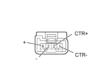
Disconnect the D51 front No. 3 speaker assembly connector.
-
Measure the resistance according to the value(s) in the table below.
Standard Resistance Tester Connection Condition Specified Condition 1 (CTR-) - 2 (CTR+) Always 40 Ω 3 (-) - 4 (+) Always 40 Ω
NG
REPLACE FRONT NO. 3 SPEAKER ASSEMBLY Click here
OK
-
-
INSPECT REAR NO. 1 SPEAKER ASSEMBLY
-
Disconnect the F11*1 and/or F12*2 rear No. 1 speaker assembly connectors.
-
*1: for RH Side
-
*2: for LH Side
-
-
Measure the resistance according to the value(s) in the table below.
Standard Resistance Tester Connection Condition Specified Condition 1 - 2 Always 4 Ω
NG
REPLACE REAR NO. 1 SPEAKER ASSEMBLY Click here
OK
-
-
REPLACE FRONT NO. 2 SPEAKER ASSEMBLY
-
Temporarily replace the front No. 2 speaker assembly with a new or normally functioning one Click here.
-
Check that the speaker sounds normally.
OK Malfunction disappears.
NG
REPLACE REAR NO. 2 SPEAKER ASSEMBLY Click here
OK
END (FRONT NO. 2 SPEAKER ASSEMBLY IS DEFECTIVE)
-
-
REPLACE REAR NO. 2 SPEAKER ASSEMBLY
-
Temporarily replace the rear No. 2 speaker assembly with a new or normally functioning one Click here.
-
Check that the speaker sounds normally.
OK Malfunction disappears.
NG
REPLACE STEREO COMPONENT AMPLIFIER ASSEMBLY Click here
OK
END (REAR NO. 2 SPEAKER ASSEMBLY IS DEFECTIVE)
-
-
REPLACE STEREO COMPONENT AMPLIFIER ASSEMBLY
-
Temporarily replace the stereo component amplifier assembly with a new or normally functioning one Click here.
-
Check that sound is emitted from the speaker normally.
OK Malfunction disappears.
NG
REPLACE RADIO AND DISPLAY RECEIVER ASSEMBLY Click here
OK
END (STEREO COMPONENT AMPLIFIER ASSEMBLY IS DEFECTIVE)
-