STEERING COLUMN ASSEMBLY (for Power Tilt and Power Telescopic Steering Column) INSTALLATION

Tech Tips
-
Use the same procedure for RHD and LHD vehicles.
-
The procedure listed below is for LHD vehicles.
-
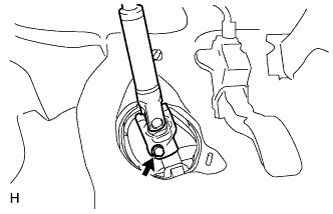
INSTALL NO. 2 STEERING INTERMEDIATE SHAFT ASSEMBLY
-
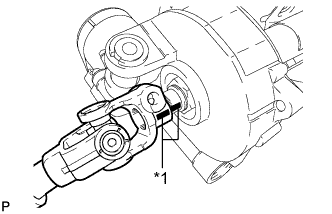
Text in Illustration *1 Matchmark Align the matchmarks on the No. 2 steering intermediate shaft assembly and steering column assembly.
-
Install the bolt.
- Torque:
- 35 N*m { 360 kgf*cm, 26 ft.*lbf }
-
-
INSTALL STEERING COLUMN PROTECTOR (for Manual Transaxle RHD)
-
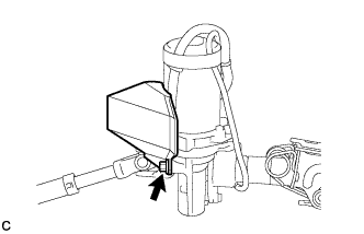
Install the steering column protector to the steering column assembly with the bolt.
- Torque:
- 25 N*m { 255 kgf*cm, 18 ft.*lbf }
-
-
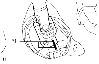
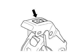
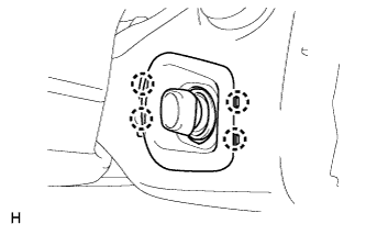
INSTALL STEERING COLUMN ASSEMBLY
-
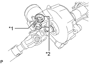
Text in Illustration *1 Collar *2 Bushing Check that the 2 bushings are securely installed to the steering column assembly.
Tech Tips
If the bushings are missing or damaged, replace the steering column assembly with a new one.
-
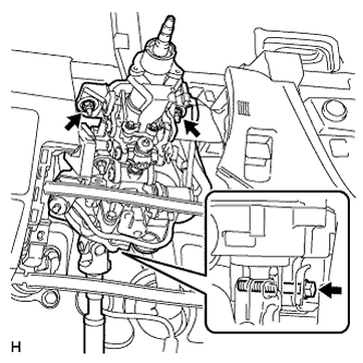
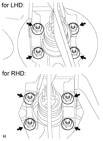
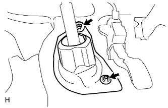
Install the steering column assembly with the bolt and 2 nuts.
- Torque:
- for nut
- 25 N*m { 255 kgf*cm, 18 ft.*lbf }
- for bolt
- 36 N*m { 367 kgf*cm, 27 ft.*lbf }
Note
-
Do not damage the 2 bushings.
-
Do not line-up the bolt hole by prying on the collar or bushings. Only install the bolt straight, without applying any force to the bushings.
-
Connect the connectors and attach the wire harness clamps to the steering column assembly and multiplex tilt and telescopic ECU.
-
Install the multiplex tilt and telescopic ECU to the steering to the steering column assembly with the nut.
- Torque:
- 25 N*m { 255 kgf*cm, 18 ft.*lbf }
-
-
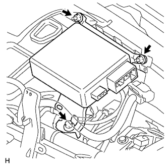
INSTALL POWER STEERING ECU ASSEMBLY (for LHD)
-
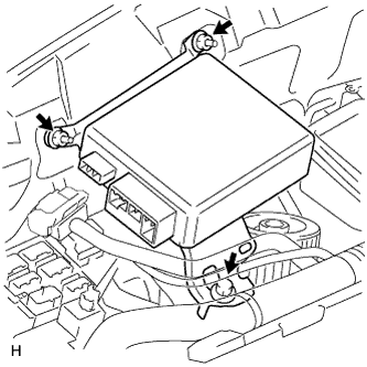
Install the power steering ECU with the bolt and 2 nuts.
- Torque:
- 8.0 N*m { 82 kgf*cm, 71 in.*lbf }
-
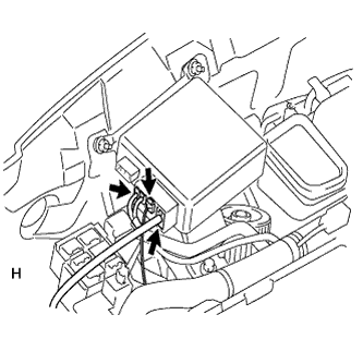
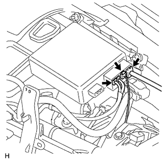
Connect the 3 connectors to the power steering ECU.
-
Connect the connector to the power steering ECU.
-
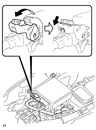
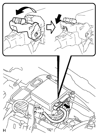
As shown in the illustration, return the lock lever to its original position to connect the connector and securely push in the lock of the lock lever.
-
Attach the wire harness clamp to the power steering ECU.
-
-
INSTALL POWER STEERING ECU ASSEMBLY (for RHD)
-
Install the power steering ECU assembly with the bolt and 2 nuts.
- Torque:
- 8.0 N*m { 82 kgf*cm, 71 in.*lbf }
-
Connect the 3 connectors to the power steering ECU assembly.
-
Connect the connector to the power steering ECU assembly.
-
As shown in the illustration, return the lock lever to its original position to connect the connector and securely push in the lock of the lock lever.
-
-
Attach the wire harness clamp to the power steering ECU assembly.
-
-
PLACE FRONT WHEELS FACING STRAIGHT AHEAD
-
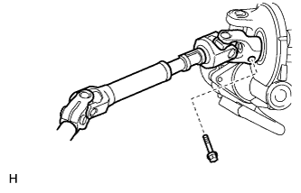
CONNECT NO. 2 STEERING INTERMEDIATE SHAFT ASSEMBLY
-
Text in Illustration *1 Matchmark Align the matchmarks on the No. 2 steering intermediate shaft assembly and steering intermediate shaft assembly.
-
Install the bolt.
- Torque:
- 35 N*m { 360 kgf*cm, 26 ft.*lbf }
-
-
INSTALL BRAKE PEDAL SUPPORT SUB-ASSEMBLY
-
Install the nut to the brake pedal support sub-assembly.
-
Install the brake pedal support sub-assembly with the 4 nuts.
- Torque:
- 13 N*m { 130 kgf*cm, 9 ft.*lbf }
-
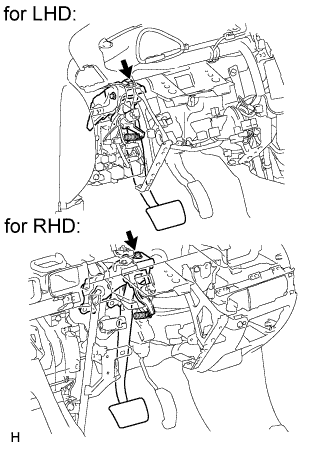
Install the brake pedal support sub-assembly to the instrument panel reinforcement with the bolt.
- Torque:
- 24 N*m { 245 kgf*cm, 18 ft.*lbf }
-
-
INSTALL LOWER NO. 1 INSTRUMENT PANEL AIRBAG ASSEMBLY
-
Install the lower No. 1 instrument panel airbag assembly Click here.
-
-
INSTALL UPPER INSTRUMENT PANEL SUB-ASSEMBLY
-
Install the upper instrument panel sub-assembly Click here.
-
-
INSTALL COLUMN HOLE COVER SILENCER SHEET
-
Install the column hole cover silencer sheet with the 2 clips.
-
Install the floor carpet.
-
-
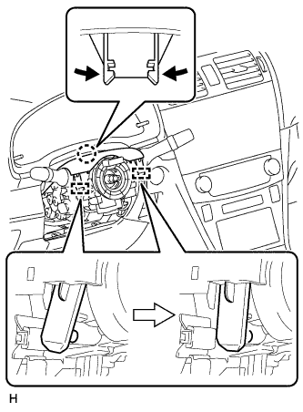
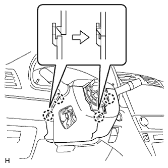
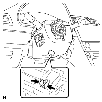
INSTALL COMBINATION SWITCH ASSEMBLY WITH SPIRAL CABLE SUB-ASSEMBLY
-
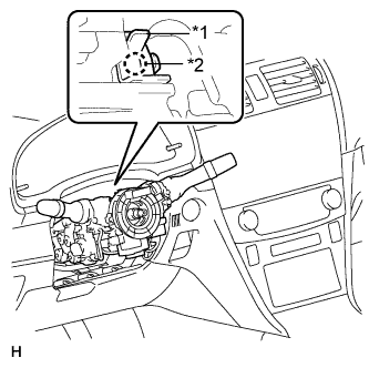
Text in Illustration *1 Clamp *2 Claw Using pliers, pinch the clamp and attach the claw to install the combination switch assembly with spiral cable sub-assembly to the steering column assembly.
-
Connect the connectors to the combination switch assembly with spiral cable sub-assembly.
-
-
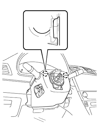
INSTALL UPPER STEERING COLUMN COVER
Note
If the steering column cover is installed in an incorrect order, it will not be possible to assemble the steering column cover.
-
Attach the claw and 2 pins to install the upper steering column cover.
-
-
INSTALL LOWER STEERING COLUMN COVER
Note
If the steering column cover is installed in an incorrect order, it will not be possible to assemble the steering column cover.
-
Attach the 2 claws to install the lower steering column cover.
-
Attach the 4 claws.
-
Attach the claw.
Tech Tips
Press the area around the claw to attach it.
-
-
INSTALL LOWER NO. 2 STEERING COLUMN COVER
-
Attach the 4 claws to install the lower No. 2 steering column cover.
-
-
ADJUST SPIRAL CABLE
-
Check that the ignition switch is off.
-
Check that the cable is disconnected from the negative (-) battery terminal.
CAUTION:
Wait at least 90 seconds after disconnecting the cable from the negative (-) battery terminal to disable the SRS system.
-
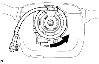
Rotate the spiral cable counterclockwise slowly by hand until it feels firm.
CAUTION:
Do not turn the spiral cable by the airbag wire harness.
-
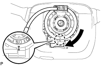
Rotate the spiral cable clockwise approximately 2.5 turns to align the marks.
CAUTION:
Do not turn the spiral cable by the airbag wire harness.
Tech Tips
The spiral cable will rotate approximately 2.5 turns to both the left and right from the center.
-
-
INSTALL STEERING WHEEL ASSEMBLY
-
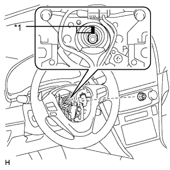
Text in Illustration *1 Matchmark Align the matchmarks on the steering wheel assembly and steering main shaft.
-
Install the steering wheel assembly set nut.
- Torque:
- 50 N*m { 510 kgf*cm, 37 ft.*lbf }
-
Connect the connectors to the spiral cable sub-assembly.
-
-
INSTALL STEERING PAD
-
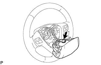
Support the steering pad with one hand.
-
Connect the connector to the steering pad.
Note
When handling the airbag connector, take care not to damage the airbag wire harness.
-
Connect the horn connector.
-
Attach the 2 springs to install the steering pad.
-
-
INSPECT STEERING WHEEL CENTER POINT
-
CONNECT CABLE TO NEGATIVE BATTERY TERMINAL
Note
-
Reset the Autoaway/Return function setting to the previous condition by changing the customize parameter Click here.
-
When disconnecting the cable, some systems need to be initialized after the cable is reconnected Click here.
-
-
INITIALIZE ROTATION ANGLE SENSOR AND CALIBRATE TORQUE SENSOR ZERO POINT
-
Initialize the rotation angle sensor and calibrate the torque sensor zero point Click here.
-
-
INSPECT SRS WARNING LIGHT
-
Inspect the SRS warning light Click here.
-