STEERING COLUMN ASSEMBLY (for Power Tilt and Power Telescopic Steering Column) REMOVAL

CAUTION:
Some of these service operations affect the SRS. Read the precautionary notices concerning the SRS before servicing the steering column Click here.
Tech Tips
-
Use the same procedure for RHD and LHD vehicles.
-
The procedure listed below is for LHD vehicles.
-
PLACE FRONT WHEELS FACING STRAIGHT AHEAD
-
DISCONNECT CABLE FROM NEGATIVE BATTERY TERMINAL
CAUTION:
Wait at least 90 seconds after disconnecting the cable from the negative (-) battery terminal to disable the SRS system.
Note
-
w/ Navigation System for HDD:
After the ignition switch is turned off, the HDD navigation system requires approximately a minute to record various types of memory and settings. As a result, after turning the ignition switch off, wait a minute or more before disconnecting the cable from the negative (-) battery terminal.
-
When disconnecting the cable, some systems need to be initialized after the cable is reconnected Click here.
-
Disable the Autoaway/Return function by changing the customize parameter Click here.
Note
Record the current customize parameter setting (whether the Autoaway/Return function is enabled or disabled) in order to restore the current setting after finishing the operation.
Tech Tips
Performing the above operation causes the Autoaway/Return function to be disabled when the ignition switch is turned off.
-
Turn the ignition switch to ON. Operate the tilt and telescopic switch to fully extend and lower the steering column.
-
Turn the ignition switch off and disconnect the cable from the negative (-) battery terminal.
-
-
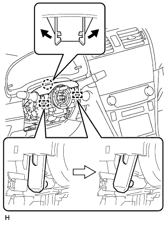
REMOVE STEERING PAD
-
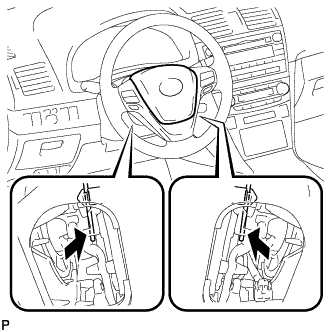
Using a screwdriver, detach the 2 springs and remove the steering pad.
-
Pull out the steering pad from the steering wheel as shown in the illustration and support the steering pad with one hand.
Note
When removing the steering pad, do not pull the airbag wire harness.
-
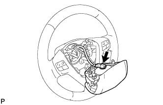
Disconnect the horn connector.
-
Disconnect the connector and remove the steering pad.
Note
When handling the airbag connector, take care not to damage the airbag wire harness.
-
-
CLEAN STEERING WHEEL ASSEMBLY
-
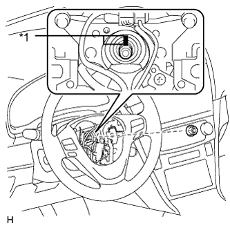
Text in Illustration *1 Matchmark Remove the steering wheel assembly set nut.
-
Put matchmarks on the steering wheel assembly and steering main shaft.
-
Disconnect the connectors from the spiral cable.
-
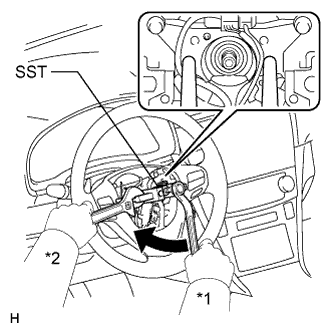
Text in Illustration *1 Turn *2 Hold Using SST, remove the steering wheel assembly.
- SST
- 09950-50013 ( 09951-05010, 09952-05010, 09953-05020, 09954-05021 )
Note
Apply a small amount of grease to the threads and tip of SST (09953-05020) before use.
-
-
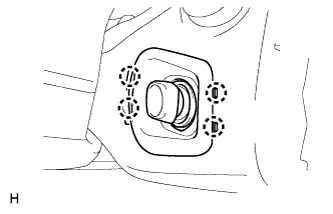
REMOVE LOWER NO. 2 STEERING COLUMN COVER
-
Detach the 4 claws and remove the lower No. 2 steering column cover.
-
-
REMOVE LOWER STEERING COLUMN COVER
Note
Removing the steering column cover in an incorrect order will cause the steering column cover to break.
-
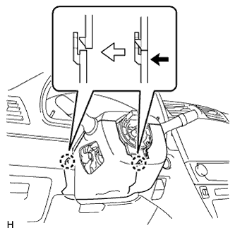
Push the right and left sides of the lower steering column cover and detach the 4 claws.
-
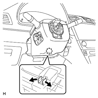
Insert fingers into the service hole of the lower steering column cover to detach the claw.
Tech Tips
Spread the claw to detach it.
-
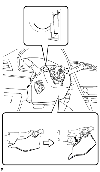
Turn the lower steering column cover to detach the 2 claws and remove the lower steering column cover as shown in the illustration.
-
-
REMOVE UPPER STEERING COLUMN COVER
Note
Removing the steering column cover in an incorrect order will cause the steering column cover to break.
-
Detach the claw and 2 pins, and remove the upper steering column cover.
-
-
REMOVE COMBINATION SWITCH ASSEMBLY WITH SPIRAL CABLE SUB-ASSEMBLY
-
Disconnect the connectors from the combination switch assembly with spiral cable sub-assembly.
-
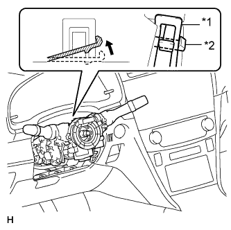
Text in Illustration *1 Clamp *2 Claw Use pliers to hold the clamp and raise the claw with a screwdriver. Remove the combination switch assembly with spiral cable sub-assembly from the steering column assembly.
-
-
REMOVE COLUMN HOLE COVER SILENCER SHEET
-
Fold back the floor carpet, and remove the 2 clips and then column hole cover silencer sheet.
-
-
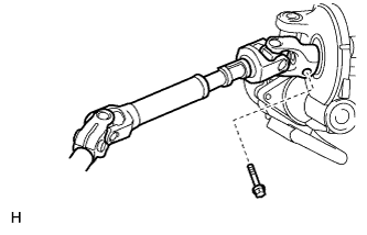
DISCONNECT NO. 2 STEERING INTERMEDIATE SHAFT ASSEMBLY
-
Remove the bolt.
Note
Do not disconnect the No. 2 steering intermediate shaft assembly from the steering intermediate shaft.
-
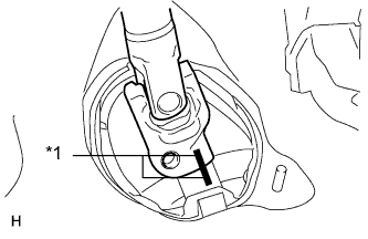
Text in Illustration *1 Matchmark Put matchmarks on the No. 2 steering intermediate shaft assembly and steering intermediate shaft.
-
Disconnect the No. 2 steering intermediate shaft assembly from the steering intermediate shaft.
-
-
REMOVE UPPER INSTRUMENT PANEL SUB-ASSEMBLY
-
Remove the upper instrument panel sub-assembly Click here.
-
-
REMOVE LOWER NO. 1 INSTRUMENT PANEL AIRBAG ASSEMBLY
-
Remove the lower No. 1 instrument panel airbag assembly Click here.
-
-
REMOVE BRAKE PEDAL SUPPORT SUB-ASSEMBLY
-
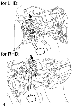
Remove the bolt and separate the brake pedal support sub-assembly from the instrument panel reinforcement.
-
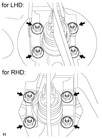
Remove the 4 nuts and brake pedal support sub-assembly.
-
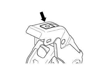
Remove the nut from the brake pedal support sub-assembly.
-
-
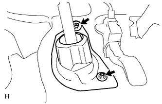
REMOVE POWER STEERING ECU ASSEMBLY (for LHD)
-
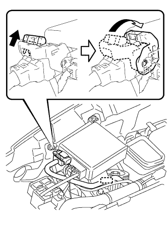
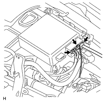
Detach the wire harness clamp from the power steering ECU.
-
Disconnect the connector from the power steering ECU.
-
As shown in the illustration, pull out the lock of the lock lever and turn the lock lever to disconnect the connector.
-
-
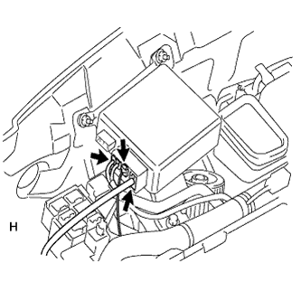
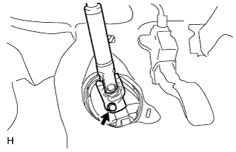
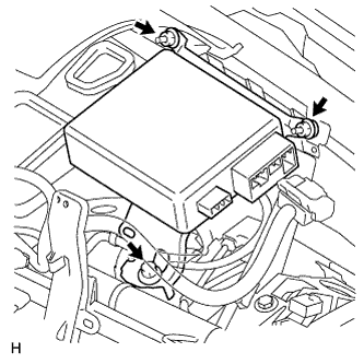
Disconnect the 3 connectors from the power steering ECU.
-
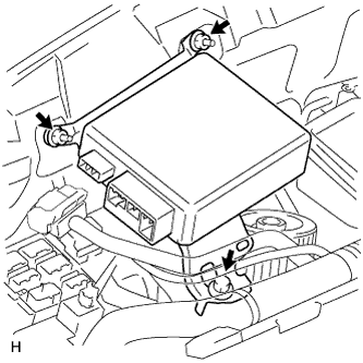
Remove the bolt, 2 nuts and power steering ECU.
-
-
REMOVE POWER STEERING ECU ASSEMBLY (for RHD)
-
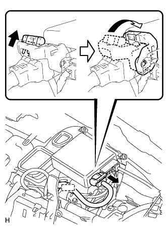
Detach the wire harness clamp from the power steering ECU.
-
Disconnect the connector from the power steering ECU.
-
As shown in the illustration, pull out the lock of the lock lever and turn the lock lever to disconnect the connector.
-
-
Disconnect the 3 connectors from the power steering ECU.
-
Remove the bolt, 2 nuts and power steering ECU.
-
-
REMOVE STEERING COLUMN ASSEMBLY
-
Disconnect the connectors and detach the wire harness clamps from the steering column assembly.
-
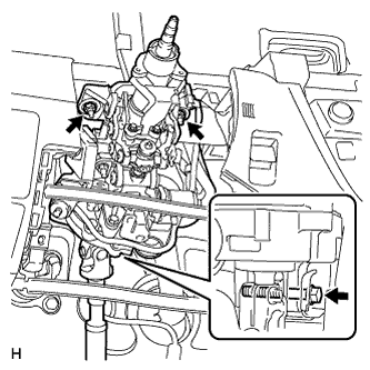
Remove the bolt, 2 nuts and steering column assembly.
Note
Do not drop or strike the steering column assembly. If dropped or struck, replace it with a new one.
-
-
CLEAN STEERING COLUMN PROTECTOR (for Manual Transaxle RHD)
-
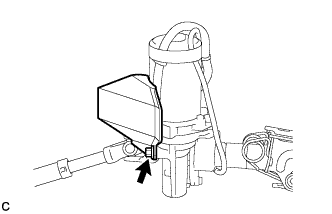
Remove the bolt and steering column protector from the steering column assembly.
-
-
REMOVE NO. 2 STEERING INTERMEDIATE SHAFT ASSEMBLY
-
Remove the bolt.
Note
Do not remove the No. 2 steering intermediate shaft assembly from the steering column assembly.
-
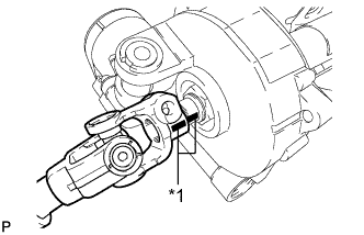
Text in Illustration *1 Matchmark Put matchmarks on the No. 2 steering intermediate shaft assembly and steering column assembly.
-
Remove the No. 2 steering intermediate shaft assembly from the steering column assembly.
-