STEERING LOCK SYSTEM TERMINALS OF ECU

-
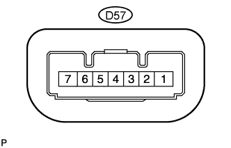
CHECK STEERING LOCK ECU (for Manual Tilt and Manual Telescopic Steering Column)
-
Disconnect the D57 steering lock ECU connector.
-
Measure the voltage and resistance according to the value(s) in the table below.
Terminal No. (Symbol) Wiring Color Terminal Description Condition Specified Condition D57-1 (GND) - Body ground W-B - Body ground Ground Always Below 1 Ω D57-6 (IG2) - D57-1 (GND) B - W-B IG2 signal input Engine switch off → engine switch on (IG) Below 1 V → 11 to 14 V D57-7 (B) - D57-1 (GND) LG - W-B Power source Always 11 to 14 V If the result is not as specified, there may be a malfunction on the wire harness side.
-
Reconnect the D57 steering lock ECU connector.
-
Measure the voltage according to the value(s) in the table below.
Terminal No. (Symbol) Wiring Color Terminal Description Condition Specified Condition D57-3 (IGE) - D57-1 (GND) P - W-B Power source for motor drive When all conditions are met:
-
Steering lock unlocked
-
Engine switch off
-
Driver side door closed → opened
11 to 14 V (Steering lock motor not operating) → Below 1 V (Steering lock motor operating) → 11 to 14 V (Steering lock motor not operating) D57-4 (SLP1) - D57-1 (GND) G - W-B Unlock position sensor output signal Steering lock locked → steering lock unlocked 11 to 14 V → Below 1.2 V If the result is not as specified, there may be a malfunction in the steering lock ECU.
-
-
-
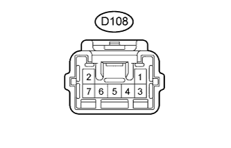
CHECK STEERING LOCK ECU (for Power Tilt and Power Telescopic Steering Column)
-
Disconnect the D108 steering lock ECU connector.
-
Measure the voltage and resistance according to the value(s) in the table below.
Terminal No. (Symbol) Wiring Color Terminal Description Condition Specified Condition D108-1 (GND) - Body ground W-B - Body ground Ground Always Below 1 Ω D108-7 (IG2) - D108-1 (GND) B - W-B IG2 signal input Engine switch off → engine switch on (IG) Below 1 V → 11 to 14 V D108-2 (B) - D108-1 (GND) LG - W-B Power source Always 11 to 14 V If the result is not as specified, there may be a malfunction on the wire harness side.
-
Reconnect the D108 steering lock ECU connector.
-
Measure the voltage according to the value(s) in the table below.
Terminal No. (Symbol) Wiring Color Terminal Description Condition Specified Condition D108-4 (IGE) - D108-1 (GND) P - W-B Power source for motor drive When all conditions are met:
-
Steering lock unlocked
-
Engine switch off
-
Driver side door closed → opened
11 to 14 V (Steering lock motor not operating) → Below 1 V (Steering lock motor operating) → 11 to 14 V (Steering lock motor not operating) D108-5 (SLP1) - D108-1 (GND) G - W-B Unlock position sensor output signal Steering lock locked → steering lock unlocked 11 to 14 V → Below 1.2 V If the result is not as specified, there may be a malfunction in the steering lock ECU.
-
-