POWER STEERING SYSTEM, Diagnostic DTC:C1511, C1512, C1513, C1514, C1517

| DTC Code | DTC Name |
|---|---|
| C1511 | Torque Sensor Circuit Malfunction |
| C1512 | Torque Sensor Circuit Malfunction |
| C1513 | Torque Sensor Circuit Malfunction |
| C1514 | Torque Sensor Power Supply Abnormal |
| C1517 | Torque Hold Abnormal |
DESCRIPTION
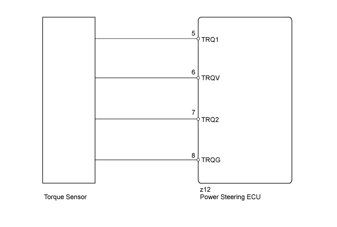
The torque sensor converts the rotation torque input to the steering wheel into an electrical signal and sends it to the power steering ECU. Based on this signal, the ECU detects steering effort.
| DTC Code | DTC Detection Condition | Trouble Area |
|---|---|---|
| C1511 | A torque sensor (TRQ1) signal error or stop. |
|
| C1512 | A torque sensor (TRQ2) signal error or stop. | |
| C1513 | The deviation between torque sensor TRQ1 and TRQ2 exceeds a specified value. | |
| C1514 | A torque sensor power supply voltage error. | |
| C1517 | Temporary control due to a malfunction related to the torque sensor continues for long time. |
WIRING DIAGRAM
INSPECTION PROCEDURE
Note
If the power steering ECU assembly or steering column assembly is replaced, perform rotation angle sensor initialization and torque sensor zero point calibration Click here.
PROCEDURE
-
CHECK CONNECTOR CONNECTION CONDITION (TORQUE SENSOR - POWER STEERING ECU)
-
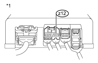
Text in Illustration *1 Component with harness connected
(Power Steering ECU)
Check the connection condition of the z12 torque sensor connector.
OK Torque sensor connector is securely connected to the power steering ECU.
NG 
CONNECT CONNECTOR SECURELY
OK 
-
-
CHECK POWER STEERING ECU (TRQV VOLTAGE)
-
Turn the ignition switch off.
-
Turn the ignition switch to ON.
-
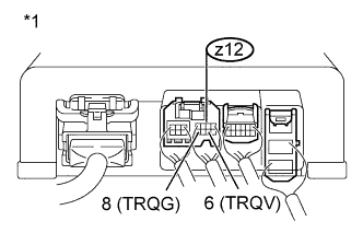
Text in Illustration *1 Component with harness connected
(Power Steering ECU)
Measure the voltage according to the value(s) in the table below.
Standard Voltage Tester Connection Switch Condition Specified Condition z12-6 (TRQV) - z12-8 (TRQG) Ignition switch ON 4.5 to 5.5 V Tech Tips
When the value is within the specified range, record the value.
Result Result Proceed to OK A NG for LHD B for RHD C
B
REPLACE POWER STEERING ECU ASSEMBLY Click here
C
REPLACE POWER STEERING ECU ASSEMBLY Click here
A
-
-
CHECK POWER STEERING ECU (TRQ1, TRQ2 VOLTAGE)
-
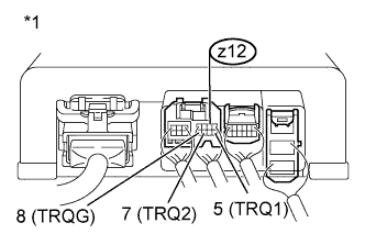
Text in Illustration *1 Component with harness connected
(Power Steering ECU)
Start the engine.
-
Measure the voltage according to the value(s) in the table below.
Standard Voltage Tester Connection Condition Specified Condition z12-5 (TRQ1) - z12-8 (TRQG) Engine running, steering wheel not turned (without load) 2.3 to 2.7 V Engine running, steering wheel turned to right with vehicle stopped 2.5 to 3.8 V Engine running, steering wheel turned to left with vehicle stopped 1.2 to 2.5 V z12-7 (TRQ2) - z12-8 (TRQG) Engine running, steering wheel not turned (without load) 2.3 to 2.7 V Engine running, steering wheel turned to right with vehicle stopped 1.2 to 2.5 V Engine running, steering wheel turned to left with vehicle stopped 2.5 to 3.8 V -
Calculate the difference between the value recorded when measuring the voltage at terminal TRQV in the previous step, and the sum of the output of torque sensor 1 and torque sensor 2.
OK 0.3 V or less (Absolute value) Result Result Proceed to OK for LHD A for RHD B NG for Manual Tilt and Manual Telescopic Steering Column C for Power Tilt and Power Telescopic Steering Column D
B
REPLACE POWER STEERING ECU ASSEMBLY Click here
C
REPLACE STEERING COLUMN ASSEMBLY Click here
D
REPLACE STEERING COLUMN ASSEMBLY Click here
A 
REPLACE POWER STEERING ECU ASSEMBLY Click here
-