BRAKE PEDAL INSTALLATION

-
INSTALL BRAKE PEDAL SUPPORT SUB-ASSEMBLY
-
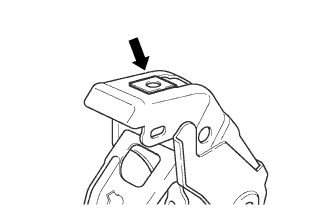
Install the nut to the brake pedal support sub-assembly.
-
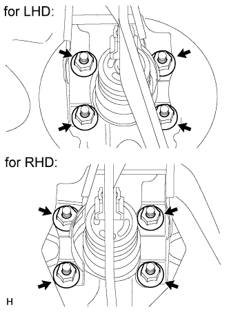
Install the brake pedal support sub-assembly with the 4 nuts.
- Torque:
- 13 N*m { 130 kgf*cm, 9 ft.*lbf }
-
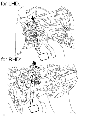
Install the brake pedal support sub-assembly to the instrument panel reinforcement with the bolt.
- Torque:
- 24 N*m { 245 kgf*cm, 18 ft.*lbf }
-
-
INSTALL STOP LIGHT SWITCH ASSEMBLY
-
Install the stop light switch assembly Click here.
-
-
INSTALL PUSH ROD PIN
-
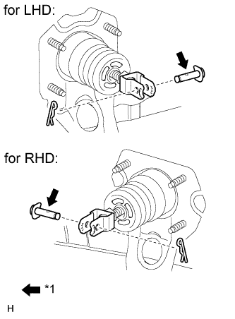
Text in Illustration *1 Lithium soap base glycol grease Apply lithium soap base glycol grease to the push rod pin.
-
Connect the brake master cylinder push rod clevis to the brake pedal with a new push rod pin and install a new clip as shown in the illustration.
-
-
INSTALL BRAKE PEDAL RETURN SPRING
-
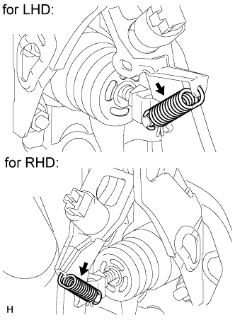
Install the brake pedal return spring between the brake pedal support sub-assembly and brake master cylinder push rod clevis.
-
-
INSPECT AND ADJUST BRAKE PEDAL HEIGHT
-
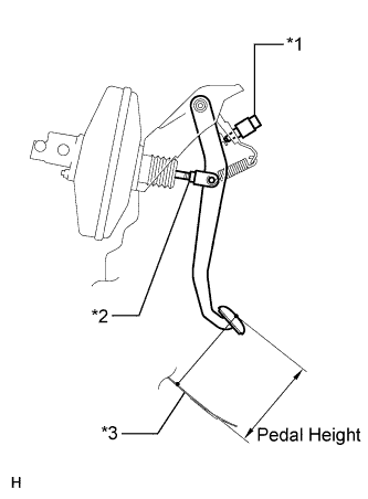
Text in Illustration *1 Stop Light Switch *2 Clevis Lock Nut *3 Floor Panel Check the brake pedal height.
-
for LHD:
Pedal Height from Floor Panel Model Specified Condition for AT 144.3 to 154.3 mm (5.68 to 6.07 in.) for MT -
for RHD:
Pedal Height from Floor Panel Model Specified Condition for AT 131.5 to 141.5 mm (5.18 to 5.57 in.) for MT 132.2 to 142.2 mm (5.20 to 5.60 in.)
-
-
Adjust the brake pedal height.
-
Disconnect the stop light switch connector.
-
Remove the stop light switch assembly.
-
Loosen the push rod clevis lock nut.
-
Adjust the brake pedal height by turning the push rod.
-
Tighten the push rod clevis lock nut.
- Torque:
- 22 N*m { 224 kgf*cm, 16 ft.*lbf }
-
Insert the stop light switch into the adjuster mounting until the switch body touches the brake pedal.
Note
Do not depress the brake pedal.
-
Turn the switch a quarter turn clockwise.
- Torque:
- 1.5 N*m { 15 kgf*cm, 13 in.*lbf, or less }
Note
Do not depress the pedal.
-
Connect the connector to the switch.
-
Check the switch clearance.
Stop light switch clearance 1.5 to 2.5 mm (0.0591 to 0.0984 in.)
-
-
-
INSPECT BRAKE PEDAL FREE PLAY
-
Stop the engine. Depress the brake pedal several times until no vacuum is left in the brake booster. Release the brake pedal.
-
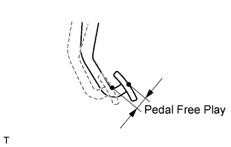
Depress the pedal until a slight resistance is felt. Measure the distance as shown in the illustration.
Pedal free play 1.0 to 6.0 mm (0.0394 to 0.236 in.) If the pedal free play is not as specified, check the stop light switch clearance. If the pedal free play is as specified, proceed to the Inspect Brake Pedal Reserve Distance procedure.
-
-
INSPECT BRAKE PEDAL RESERVE DISTANCE
Tech Tips
Measure the distance at the same point used for the brake pedal height inspection.
-
Release the parking brake.
-
With the engine running, depress the brake pedal and measure the pedal reserve distance.
Pedal Reserve Distance from the Floor Panel at 294 N (30 kgf, 66 lbf): 87 mm (3.43 in.) If the distance is not as specified, troubleshoot the brake system Click here.
-
-
INSTALL LOWER NO. 1 INSTRUMENT PANEL AIRBAG ASSEMBLY
-
Install the lower No. 1 instrument panel airbag assembly Click here.
-
-
INSTALL UPPER INSTRUMENT PANEL SUB-ASSEMBLY
-
Install the upper instrument panel sub-assembly Click here.
-