REAR BRAKE INSTALLATION

-
INSTALL REAR DISC
-
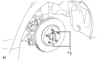
Text in Illustration *1 Matchmark Align the matchmarks of the disc and axle hub and install the disc.
Note
When replacing the disc with a new one, select the installation position where the rear disc has minimal runout.
-
-
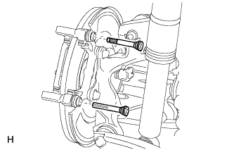
INSTALL REAR DISC BRAKE CYLINDER MOUNTING
-
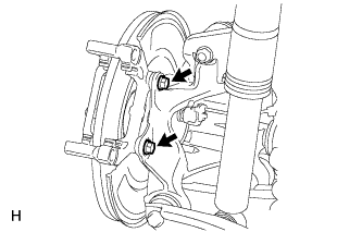
Install the rear disc brake cylinder mounting to the axle carrier with the 2 bolts.
- Torque:
- for bolt M10
- 57 N*m { 585 kgf*cm, 42 ft.*lbf }
- for bolt M12
- 101 N*m { 1030 kgf*cm, 74 ft.*lbf }
-
-
INSTALL REAR DISC BRAKE BUSH DUST BOOT
-
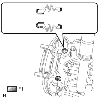
Text in Illustration *1 Lithium soap base glycol grease Apply a light coat of lithium soap base glycol grease to the entire circumference of 2 new rear disc brake bush dust boots where they contact the rear disc brake cylinder mounting, and the entire inner circumference of both ends of the boots.
Note
Apply a sufficient amount of lithium soap base glycol grease to the entire circumference of the rear disc brake bush dust boot and rear disc brake cylinder mounting contact surfaces.
Tech Tips
Apply at least 0.3 g (0.01 oz.) of lithium soap base glycol grease to the rear disc brake bush dust boot.
-
Install the 2 rear disc brake bush dust boots to the rear disc brake cylinder mounting.
-
-
INSTALL REAR DISC BRAKE CYLINDER SLIDE BUSH
-
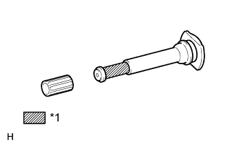
Text in Illustration *1 Lithium soap base glycol grease Apply lithium soap base glycol grease to the rear disc brake cylinder slide pin, as shown in the illustration.
-
Install a new rear disc brake cylinder slide bush to the rear disc brake cylinder slide pin.
-
-
INSTALL REAR DISC BRAKE CYLINDER SLIDE PIN
-
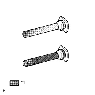
Text in Illustration *1 Lithium soap base glycol grease Apply lithium soap base glycol grease to the sliding part and the seal surface of the 2 rear disc brake cylinder slide pins.
-
Install the 2 rear disc brake cylinder slide pins to the rear disc brake cylinder mounting.
-
-
INSTALL REAR DISC BRAKE PAD SUPPORT PLATE
-
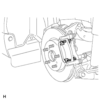
Install the 4 rear disc brake pad support plates to the rear disc brake cylinder mounting.
Note
Be sure to install each rear disc brake pad support plate in the correct position and direction.
-
-
INSTALL REAR DISC BRAKE PAD
-
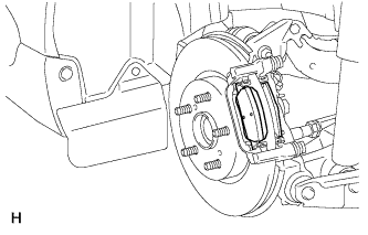
Install the 2 rear disc brake pads to the rear disc brake cylinder mounting.
Note
Make sure there is no oil or grease on the friction surfaces of the disc brake pads or the rear disc.
-
-
INSTALL REAR DISC BRAKE CYLINDER ASSEMBLY
-
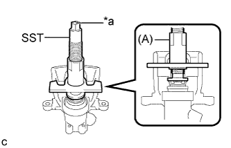
To compensate for pad lining thickness, use SST to adjust the protrusion of the rear disc brake piston using the procedure below:
-
Set SST to the rear disc brake cylinder assembly as shown in the illustration.
- SST
- 09719-12010 ( 09719-01010, 09719-01020, 09719-01030 )
- 09719-12020
Text in Illustration *a Identification Mark Tech Tips
Using the following table, select SST in accordance with the rear disc brake cylinder assembly that is being installed.
SST Identification Mark for LH Side 09719-12020
(Left-hand Threads)
L for RH Side 09719-01010
(Right-hand Threads)
R -
Turn SST (A) to secure it to the rear disc brake cylinder assembly.
-
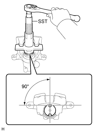
Turn SST to adjust the protrusion of the rear disc brake piston.
Note
-
Place the rear disc between the 2 rear disc brake pads and determine the piston return value.
-
Turn the rear disc brake piston to the position where the protrusion on the pad lines up properly with the piston groove.
-
-
-
Hold the rear disc brake cylinder slide pin, and install the rear disc brake cylinder assembly to the rear disc brake cylinder mounting with the 2 bolts.
- Torque:
- 30 N*m { 306 kgf*cm, 22 ft.*lbf }
-
-
CONNECT REAR BRAKE FLEXIBLE HOSE
-
Install a new gasket and connect the flexible hose to the rear disc brake cylinder assembly with a new union bolt.
- Torque:
- 29 N*m { 296 kgf*cm, 21 ft.*lbf }
Tech Tips
Install the flexible hose lock securely into the lock hole in the disc brake cylinder.
-
-
ADJUST BUILT-IN CLEARANCE
-
Secure the rear disc with one of the wheel nuts.
- Torque:
- Maximum tightening torque
- 10 N*m { 102 kgf*cm, 7 ft.*lbf }
-
Make sure the rear disc is restrained.
-
Start the engine.
-
Depress brake pedal slowly (around 3 seconds) for 5 times.*1
-
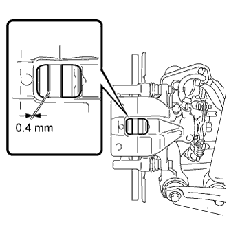
Using a thickness gauge, check the clearance between the outer pad and disc is less than 0.4 mm (0.0158 in.) when caliper is pushed fully outward.*2
-
If necessary repeat *1 and *2 steps.
-
Stop the engine.
-
Remove the wheel nut temporarily secured on the disc.
-
-
CONNECT NO. 3 PARKING BRAKE CABLE ASSEMBLY
-
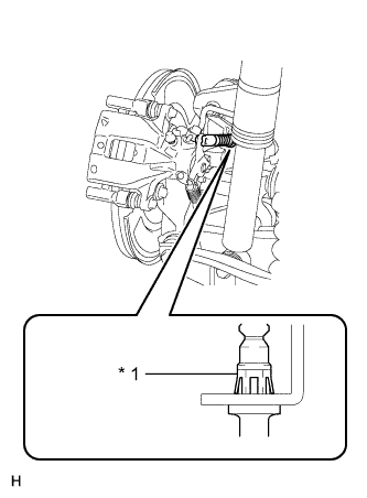
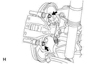
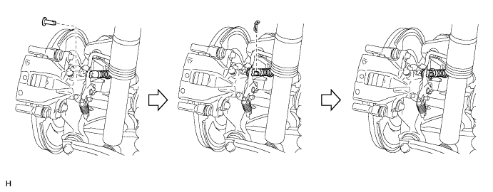
Text in Illustration *1 Claw Attach the claw of the No. 3 parking brake cable assembly to the rear disc brake cylinder assembly, as shown in the illustration.
-
Connect the No. 3 parking brake cable assembly with the pin and new clip to the rear disc brake cylinder assembly.
Note
-
The pin and clip must be installed as shown in the illustration.
-
Make sure that the cable boot is not damaged and that the cable is securely connected.
-
If the boot is twisted, it can be adjusted by hand by up to 45° in either direction.
-
-
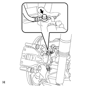
Attach the clamp to the trailing arm.
-
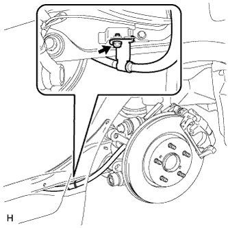
Install the bolt.
- Torque:
- 6.0 N*m { 61 kgf*cm, 53 in.*lbf }
-
-
INSTALL PARKING BRAKE LEVER PROTECTOR
-
REMOVE CENTER COWL TOP VENTILATOR LOUVER
-
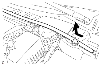
Slide the hood to cowl top seal and detach the clip as shown in the illustration.
-
Detach the 5 claws and remove the center cowl top ventilator louver.
-
-
FILL RESERVOIR WITH BRAKE FLUID
-
Fill the reservoir with brake fluid.
Brake Fluid SAE J1704 or FMVSS No. 116 DOT 4 Note
Add brake fluid to keep the level between the MIN and MAX lines of the reservoir while bleeding the brakes.
-
-
BLEED BRAKE LINE
Note
-
Bleed the brake line of the wheel farthest from the master cylinder first.
-
Add brake fluid to keep the level between the MIN and MAX lines of the reservoir while bleeding the brakes.
-
Connect a vinyl tube to the bleeder plug.
-
Depress the brake pedal several times, and then loosen the bleeder plug with the pedal depressed.*1
-
When fluid stops coming out, tighten the bleeder plug, and then release the brake pedal.*2
-
Repeat *1 and *2 until all the air in the fluid is completely bled out.
-
Tighten the bleeder plug completely.
- Torque:
- 10 N*m { 102 kgf*cm, 7 ft.*lbf }
-
Repeat the above procedure for each wheel to bleed the brake line.
-
-
BLEED CLUTCH LINE (for 1AD-FTV)
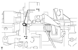
Text in Illustration *1 Bleeder Plug Cap *2 Bleeder Plug
-
Remove the bleeder plug cap.
-
Connect a vinyl tube to the bleeder plug.
-
Depress the clutch pedal several times, and then loosen the bleeder plug while the pedal is depressed.
-
When fluid no longer comes out, tighten the bleeder plug, and then release the clutch pedal.
-
Repeat the previous 2 steps until all the air in the fluid is completely bled.
-
Tighten the bleeder plug.
- Torque:
- 8.4 N*m { 86 kgf*cm, 74 in.*lbf }
-
Install the bleeder plug cap.
-
Check that all the air has been bled from the clutch line.
-
-
BLEED CLUTCH LINE (for 2AD-FHV)
Text in Illustration *1 Bleeder Plug Cap *2 Bleeder Plug
-
Remove the bleeder plug cap.
-
Connect a vinyl tube to the bleeder plug.
-
Depress the clutch pedal several times, and then loosen the bleeder plug while the pedal is depressed.
-
When fluid no longer comes out, tighten the bleeder plug, and then release the clutch pedal.
-
Repeat the previous 2 steps until all the air in the fluid is completely bled.
-
Tighten the bleeder plug.
- Torque:
- 8.4 N*m { 86 kgf*cm, 74 in.*lbf }
-
Install the bleeder plug cap.
-
Check that all the air has been bled from the clutch line.
-
-
BLEED CLUTCH LINE (for 2AD-FTV)
Text in Illustration *1 Bleeder Plug Cap *2 Bleeder Plug
-
Remove the bleeder plug cap.
-
Connect a vinyl tube to the bleeder plug.
-
Depress the clutch pedal several times, and then loosen the bleeder plug while the pedal is depressed.
-
When fluid no longer comes out, tighten the bleeder plug, and then release the clutch pedal.
-
Repeat the previous 2 steps until all the air in the fluid is completely bled.
-
Tighten the bleeder plug.
- Torque:
- 8.4 N*m { 86 kgf*cm, 74 in.*lbf }
-
Install the bleeder plug cap.
-
Check that all the air has been bled from the clutch line.
-
-
INSPECT FOR BRAKE FLUID LEAK
-
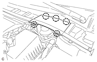
INSTALL CENTER COWL TOP VENTILATOR LOUVER
-
Attach the 5 claws to install the center cowl top ventilator louver.
-
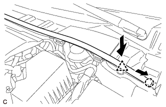
Push and attach the clip, and slide and attach the claw of the hood to cowl top seal as shown in the illustration.
-
-
INSPECT BRAKE FLUID LEVEL
-
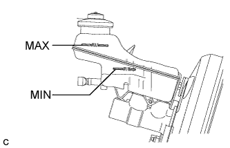
Check the fluid level.
If the brake fluid level is lower than the MIN line, check for leaks and inspect the disc brake pads. If necessary, refill the reservoir with brake fluid to the MAX line after repair or replacement.
Brake Fluid SAE J1704 or FMVSS No. 116 DOT 4
-
-
CANCEL PARKING BRAKE FULL RELEASE MODE
-
Turn the ignition switch to ON.
-
Press and hold the electric parking brake switch for 5 seconds to cancel parking brake full release mode.
-
-
INSTALL REAR WHEEL
- Torque:
- 103 N*m { 1050 kgf*cm, 76 ft.*lbf }