VEHICLE STABILITY CONTROL SYSTEM Slip Indicator Light Remains ON
DESCRIPTION
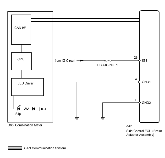
The skid control ECU is connected to the combination meter via CAN communication.
If the skid control ECU stores a DTC, the slip indicator light in the combination meter comes on.
The slip indicator light blinks during VSC and/or TRC operation.
When the system fails, the slip indicator light comes on to warn the driver Click here.
WIRING DIAGRAM
INSPECTION PROCEDURE
Note
When replacing the skid control ECU (Brake actuator assembly), perform the engine variant learning Click here.
PROCEDURE
-
CHECK CAN COMMUNICATION SYSTEM
-
Check if a CAN communication system DTC is output Click here.
Result Result Proceed to DTC is not output. A DTC is output. B
B 
GO TO CAN COMMUNICATION SYSTEM (HOW TO PROCEED WITH TROUBLESHOOTING) Click here
A 
-
-
CHECK IF SKID CONTROL ECU CONNECTOR IS SECURELY CONNECTED
-
Check if the skid control ECU connector is securely connected.
OK The connector is securely connected.
NG
CONNECT CONNECTOR TO ECU CORRECTLY
OK
-
-
CHECK HARNESS AND CONNECTOR (IG1 TERMINAL)
-
Turn the ignition switch off.
-
Disconnect the skid control ECU connector.
-
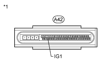
Text in Illustration *1 Front view of wire harness connector
(to Skid Control ECU)
Measure the voltage according to the value(s) in the table below.
Standard Voltage Tester Connection Switch Condition Specified Condition A42-28 (IG1) - Body ground Ignition switch ON 11 to 14 V
NG
REPAIR OR REPLACE HARNESS OR CONNECTOR
OK
-
-
CHECK HARNESS AND CONNECTOR (GND1, GND2 TERMINAL)
-
Turn the ignition switch off.
-
Disconnect the skid control ECU connector.
-
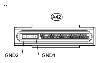
Text in Illustration *1 Front view of wire harness connector
(to Skid Control ECU)
Measure the resistance according to the value(s) in the table below.
Standard Resistance Tester Connection Condition Specified Condition A42-4 (GND1) - Body ground Always Below 1 Ω A42-1 (GND2) - Body ground Always Below 1 Ω
NG
REPAIR OR REPLACE HARNESS OR CONNECTOR
OK
-
-
INSPECT COMBINATION METER ASSEMBLY
-
Perform the Active Test of the combination meter to check the slip indicator light using the intelligent tester Click here.
OK The slip indicator light turns on or off in accordance with the intelligent tester operation. Tech Tips
If troubleshooting has been carried out according to the Problem Symptoms Table, refer back to the table and proceed to the next step before replacing the part Click here.
NG
REPLACE COMBINATION METER ASSEMBLY Click here
OK 
REPLACE BRAKE ACTUATOR ASSEMBLY Click here
-