VEHICLE STABILITY CONTROL SYSTEM, Diagnostic DTC:C1249/49

| DTC Code | DTC Name |
|---|---|
| C1249/49 | Open in Stop Light Switch Circuit |
DESCRIPTION
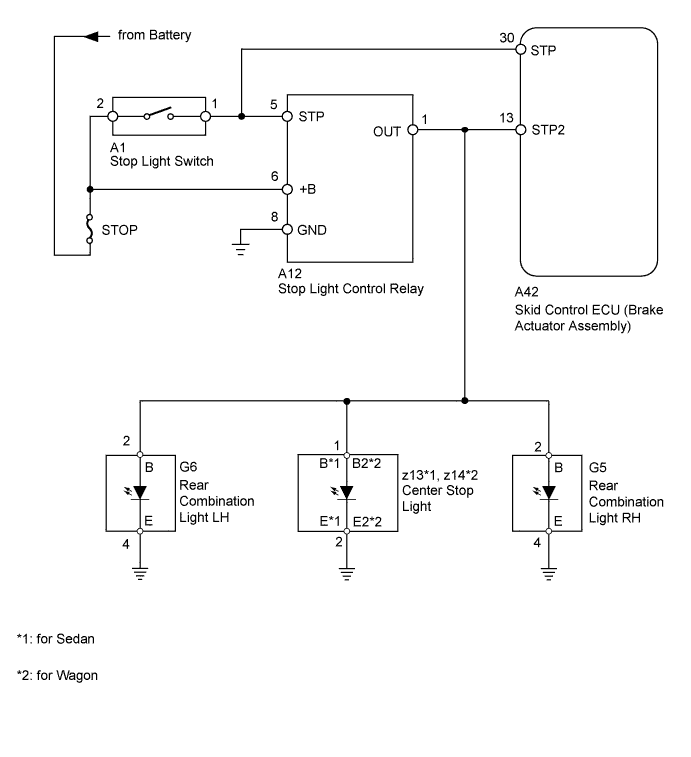
The skid control ECU (housed in the brake actuator assembly) receives the stop light switch signal and determines the condition of brake operation.
The skid control ECU has an open detection circuit which stores this DTC when detecting an open in the stop light input line or the ground line of the stop light circuit with the stop light switch off (brake pedal not depressed).
| DTC Code | DTC Detection Condition | Trouble Area |
|---|---|---|
| C1249/49 | Stop light switch circuit malfunction. |
|
WIRING DIAGRAM
INSPECTION PROCEDURE
Note
-
When replacing the skid control ECU (brake actuator assembly), perform the engine variant learning Click here.
-
Inspect the fuses for circuits related to this system before performing the following inspection procedure.
PROCEDURE
-
CHECK STOP LIGHT OPERATION
-
Check that the stop lights come on when the brake pedal is depressed, and go off when the brake pedal is released.
OK Condition Illumination Condition Brake pedal depressed ON Brake pedal released OFF
NG 
INSPECT STOP LIGHT SWITCH Click here
OK 
-
-
CHECK HARNESS AND CONNECTOR (STP TERMINAL)
-
Disconnect the skid control ECU connector.
-
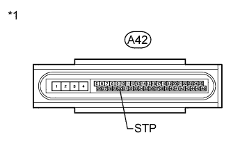
Text in Illustration *1 Front view of wire harness connector
(to Skid Control ECU)
Measure the voltage according to the value(s) in the table below.
Standard Voltage Tester Connection Switch Condition Specified Condition A42-30 (STP) - Body ground Stop light switch on (Brake pedal depressed) 8 to 14 V Stop light switch off (Brake pedal released) Below 1.5 V
NG 
REPAIR OR REPLACE HARNESS OR CONNECTOR
OK
-
-
CHECK HARNESS AND CONNECTOR (STP2 TERMINAL)
-
Disconnect the skid control ECU connector.
-
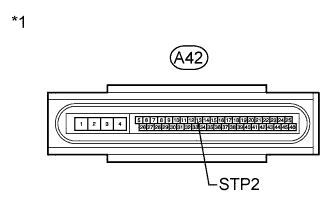
Text in Illustration *1 Front view of wire harness connector
(to Skid Control ECU)
Measure the voltage according to the value(s) in the table below.
Standard Voltage Tester Connection Switch Condition Specified Condition A42-13 (STP2) - Body ground Stop light switch on (Brake pedal depressed) 8 to 14 V Stop light switch off (Brake pedal released) Below 1.5 V
NG
REPAIR OR REPLACE HARNESS OR CONNECTOR
OK
-
-
RECONFIRM DTC
-
Clear the DTCs Click here.
-
Start the engine.
-
Depress the brake pedal several times to test the stop light circuit.
-
Check if the same DTC is output Click here.
Result Result Proceed to DTC C1249/49 is output. A DTC C1249/49 is not output. B
B
USE SIMULATION METHOD TO CHECK Click here
A 
REPLACE BRAKE ACTUATOR ASSEMBLY Click here
-
-
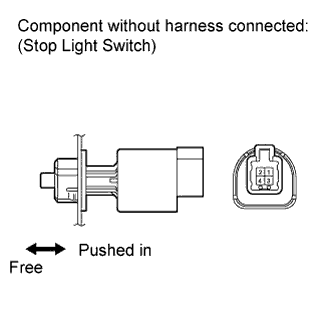
INSPECT STOP LIGHT SWITCH
-
Remove the stop light switch Click here.
-
Measure the resistance according to the value(s) in the table below.
Standard Resistance Tester Connection Switch Condition Specified Condition 1 - 2 Switch pin free Below 1 Ω Switch pin pushed in 10 kΩ or higher
NG
REPLACE STOP LIGHT SWITCH Click here
OK
-
-
CHECK HARNESS AND CONNECTOR (STOP LIGHT SWITCH - BATTERY)
-
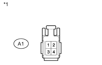
Text in Illustration *1 Front view of wire harness connector
(to Stop Light Switch)
Disconnect the A1 stop light switch connector.
-
Measure the voltage according to the value(s) in the table below.
Standard Voltage Tester Connection Condition Specified Condition A1-2 - Body ground Always 11 to 14 V
NG
REPAIR OR REPLACE HARNESS OR CONNECTOR
OK
-
-
CHECK HARNESS AND CONNECTOR (STOP LIGHT CONTROL RELAY - BATTERY)
-
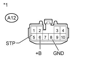
Text in Illustration *1 Front view of wire harness connector
(to Stop Light Control Relay)
Disconnect the A12 stop light control relay connector.
-
Measure the voltage according to the value(s) in the table below.
Standard Voltage Tester Connection Condition Specified Condition A12-5 (STP) - Body ground Brake pedal depressed 11 to 14 V A12-5 (STP) - Body ground Brake pedal released Below 1 V A12-6 (+B) - Body ground Always 11 to 14 V -
Measure the resistance according to the value(s) in the table below.
Standard Resistance Tester Connection Condition Specified Condition A12-8 (GND) - Body ground Always Below 1 Ω
NG
REPAIR OR REPLACE HARNESS OR CONNECTOR
OK
-
-
CHECK HARNESS AND CONNECTOR (STOP LIGHT CONTROL RELAY - REAR COMBINATION LIGHT AND CENTER STOP LIGHT)
-
Disconnect the skid control ECU connector.
-
Disconnect the stop light control relay connector.
-
Rear Combination Light:
-
Disconnect the rear combination light connector.
-
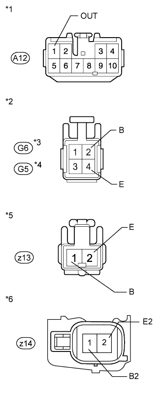
Text in Illustration *1 Front view of wire harness connector
(to Stop Light Control Relay)
*2 Front view of wire harness connector
(to Rear Combination Light)
*3 for LH *4 for RH *5 Front view of wire harness connector
(to Center Stop Light [for Sedan])
*6 Front view of wire harness connector
(to Center Stop Light [for Wagon])
Measure the resistance according to the value(s) in the table below.
Standard Resistance for LH Tester Connection Condition Specified Condition A12-1 (OUT) - G6-2 (B) Always Below 1 Ω G6-4 (E) - Body ground Always Below 1 Ω G6-2 (B) - Body ground Always 10 kΩ or higher for RH Tester Connection Condition Specified Condition A12-1 (OUT) - G5-2 (B) Always Below 1 Ω G5-4 (E) - Body ground Always Below 1 Ω G5-2 (B) - Body ground Always 10 kΩ or higher
-
-
Center Stop Light:
-
Disconnect the center stop light connector.
-
Measure the resistance according to the value(s) in the table below.
Standard Resistance for Sedan Tester Connection Condition Specified Condition A12-1 (OUT) - z13-1 (B) Always Below 1 Ω z13-2 (E) - Body ground Always Below 1 Ω z13-1 (B) - Body ground Always 10 kΩ or higher for Wagon Tester Connection Condition Specified Condition A12-1 (OUT) - z14-1 (B2) Always Below 1 Ω z14-2 (E2) - Body ground Always Below 1 Ω z14-1 (B2) - Body ground Always 10 kΩ or higher
-
NG
REPAIR OR REPLACE HARNESS OR CONNECTOR
OK
-
-
CHECK HARNESS AND CONNECTOR (SKID CONTROL ECU - STOP LIGHT CONTROL RELAY)
-
Disconnect the skid control ECU connector.
-
Disconnect the stop light control relay connector.
-
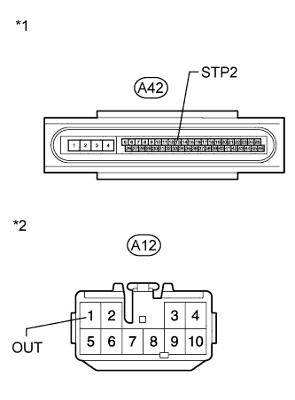
Text in Illustration *1 Front view of wire harness connector
(to Skid Control ECU)
*2 Front view of wire harness connector
(to Stop Light Control Relay)
Measure the resistance according to the value(s) in the table below.
Standard Resistance Tester Connection Condition Specified Condition A42-13 (STP2) - A12-1 (OUT) Always Below 1 Ω
NG
REPAIR OR REPLACE HARNESS OR CONNECTOR
OK
-
-
REPLACE REPLACE STOP LIGHT CONTROL RELAY ASSEMBLY
-
Replace the stop light control relay assembly (for LHD: Click here, for RHD: Click here.
NEXT
-
-
RECONFIRM DTC
-
Clear the DTCs Click here.
-
Start the engine.
-
Depress the brake pedal several times to test the stop light circuit.
-
Check if the same DTC is output Click here.
Result Result Proceed to DTC C1249/49 is output. A DTC C1249/49 is not output. B
B
END
A
REPLACE BRAKE ACTUATOR ASSEMBLY Click here
-