VEHICLE STABILITY CONTROL SYSTEM Skid Control Buzzer Circuit
DESCRIPTION
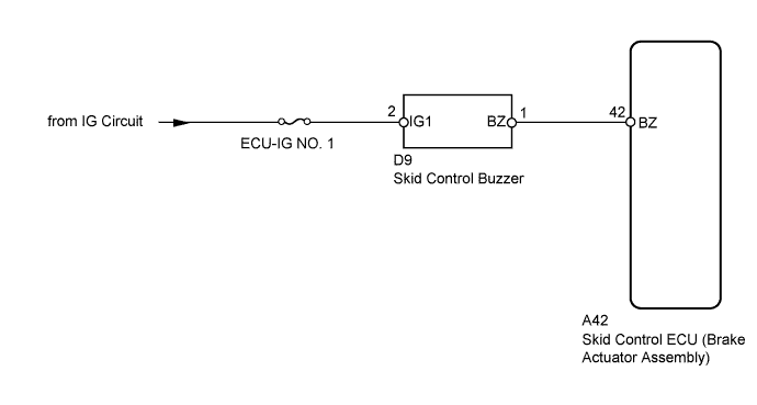
The skid control buzzer sounds upon receiving a signal from the skid control ECU.
WIRING DIAGRAM
INSPECTION PROCEDURE
Note
When replacing the skid control ECU (brake actuator assembly), perform the engine variant learning Click here.
PROCEDURE
-
PERFORM ACTIVE TEST USING INTELLIGENT TESTER (DSS SIGNAL BUZZER)
-
Connect the intelligent tester to the DLC3.
-
Start the engine.
-
Select the Active Test mode on the intelligent tester Click here.
ABS/VSC/TRC Tester Display Test Part Control Range Diagnostic Note DSS Signal Buzzer Skid control buzzer Buzzer ON / OFF Buzzer can be heard. -
Check that the buzzer sounds/stops when turning the skid control buzzer on/off by using the intelligent tester.
Result Result Proceed to Buzzer does not sound or sounds constantly. A Buzzer sounds/stops. B Tech Tips
If troubleshooting has been carried out according to the Problem Symptoms Table, refer back to the table and proceed to the next step Click here.
B 
USE SIMULATION METHOD TO CHECK Click here
A 
-
-
CHECK HARNESS AND CONNECTOR (SKID CONTROL BUZZER POWER SOURCE TERMINAL)
-
Turn the ignition switch off.
-
Disconnect the skid control buzzer connector.
-
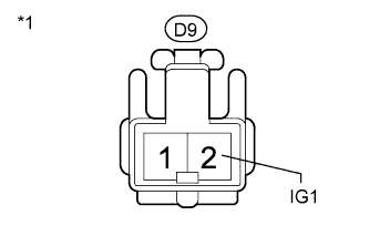
Text in Illustration *1 Front view of wire harness connector
(to Skid Control Buzzer)
Measure the voltage according to the value(s) in the table below.
Standard Voltage Tester Connection Switch Condition Specified Condition D9-2 (IG1) - Body ground Ignition switch ON 11 to 14 V
NG
REPAIR OR REPLACE HARNESS OR CONNECTOR
OK
-
-
INSPECT SKID CONTROL BUZZER
-
Turn the ignition switch off.
-
Remove the skid control buzzer Click here.
-
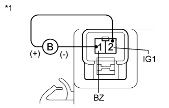
Text in Illustration *1 Component without harness connected
(Skid Control Buzzer)
Connect the negative (-) battery terminal to terminal 1 (BZ) of the skid control buzzer, and the positive (+) battery terminal to terminal 2 (IG1), and then check that the buzzer sounds.
OK The skid control buzzer sounds.
NG
REPLACE SKID CONTROL BUZZER Click here
OK
-
-
CHECK HARNESS AND CONNECTOR (SKID CONTROL BUZZER - SKID CONTROL ECU)
-
Disconnect the skid control buzzer connector.
-
Disconnect the skid control ECU connector.
-
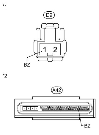
Text in Illustration *1 Front view of wire harness connector
(to Skid Control Buzzer)
*2 Front view of wire harness connector
(to Skid Control ECU)
Measure the resistance according to the value(s) in the table below.
Standard Resistance Tester Connection Condition Specified Condition D9-1 (BZ) - A42-42 (BZ) Always Below 1 Ω D9-1 (BZ) - Body ground Always 10 kΩ or higher
NG
REPAIR OR REPLACE HARNESS OR CONNECTOR
OK 
REPLACE BRAKE ACTUATOR ASSEMBLY Click here
-