REAR WHEEL ALIGNMENT ADJUSTMENT

-
INSPECT TIRES
-
Check the tires for wear and proper inflation pressure.
Cold Tire Inflation Pressure Tire Size Vehicle Speed Front Rear 205/60R16 92V Driving below 160 km/h
(100 mph)
250 kPa (2.5 kgf/cm2, 37 psi)
220 kPa (2.2 kgf/cm2, 32 psi)
Driving over 160 km/h
(100 mph)
280 kPa (2.8 kgf/cm2, 41 psi)
250 kPa (2.5 kgf/cm2, 37 psi)
215/55R17 94W Driving below 160 km/h
(100 mph)
240 kPa (2.4 kgf/cm2, 35 psi)
230 kPa (2.3 kgf/cm2, 34 psi)
Driving over 160 km/h
(100 mph)
280 kPa (2.8 kgf/cm2, 41 psi)
270 kPa (2.7 kgf/cm2, 40 psi)
215/55R17 94W
(for Eco Package)
Driving below 160 km/h
(100 mph)
270 kPa (2.7 kgf/cm2, 40 psi)
250 kPa (2.5 kgf/cm2, 37 psi)
Driving over 160 km/h
(100 mph)
310 kPa (3.1 kgf/cm2, 45 psi)
290 kPa (2.9 kgf/cm2, 43 psi)
225/45R18 95W Driving below 160 km/h
(100 mph)
270 kPa (2.7 kgf/cm2, 40 psi)
230 kPa (2.3 kgf/cm2, 34 psi)
Driving over 160 km/h
(100 mph)
310 kPa (3.1 kgf/cm2, 45 psi)
270 kPa (2.7 kgf/cm2, 40 psi)
T145/70D17 106M - 420 kPa (4.2 kgf/cm2, 60 psi)
-
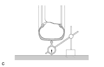
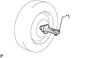
Using a dial indicator, check the runout of the tires.
Tire runout 1.0 mm (0.0394 in.) or less
-
-
MEASURE VEHICLE HEIGHT
Note
-
Before inspecting the wheel alignment, adjust the vehicle height to the specified value.
-
Be sure to perform the measurement on a level surface.
-
If it is necessary to go under the vehicle for measurement, make sure that the parking brake is applied and the vehicle is secured with chocks.
-
Bounce the vehicle up and down at the corners several times to stabilize the suspension.
-
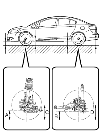
Measure the vehicle height.
Measuring points A Ground clearance of front lower suspension arm bushing set bolt center B Ground clearance of rear suspension arm No. 2 bushing set bolt center C Ground clearance of front wheel center D Ground clearance of rear wheel center Standard Vehicle Height (Unloaded Vehicle) except Rough Road Package 1 Front C - A Rear D - B 101 mm (3.98 in.) 62 mm (2.44 in.) Standard Vehicle Height (Unloaded Vehicle) for Rough Road Package 1 Front C - A Rear D - B 94 mm (3.70 in.) 46 mm (1.81 in.) Note
The standard value shown here is a value that is used for adjusting the wheel alignment and does not indicate the height of an actual vehicle.
-
-
INSPECT TOE-IN
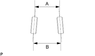
Standard Toe-in (Unloaded Vehicle) except Rough Road Package 1 Item Specified Condition Toe-in B - A: 1.8 +/-2 mm (0.07 +/-0.08 in.) Standard Toe-in (Unloaded Vehicle) for Rough Road Package 1 Item Specified Condition Toe-in B - A: 0.3 +/-2 mm (0.01 +/-0.08 in.) If the toe-in is not within the specified range, inspect the suspension parts and replace them if necessary.
-
ADJUST TOE-IN (for Cam Type)
-
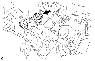
Loosen the nut of the rear No. 1 suspension arm assembly (at the rear suspension member side).
Note
Hold the rear suspension toe adjust cam sub-assembly while rotating the nut.
-
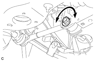
Rotate the rear suspension toe adjust cam sub-assembly to adjust the toe-in.
Adjustment Value except Rough Road Package 1 Item Specified Condition Toe-in B - A: 1.8 +/-2 mm (0.07 +/-0.08 in.) Adjustment Value for Rough Road Package 1 Item Specified Condition Toe-in B - A: 0.3 +/-2 mm (0.01 +/-0.08 in.) Tech Tips
Rotating the rear suspension toe adjust cam sub-assembly by one notch changes the toe by approximately 3.4 mm (0.134 in.).
-
Tighten the nut of the rear No. 1 suspension arm assembly (at the rear suspension member side).
- Torque:
- 100 N*m { 1020 kgf*cm, 74 ft.*lbf }
Note
-
Hold the rear suspension toe adjust cam sub-assembly while rotating the nut.
-
Make sure that all tires of the vehicle are on the ground and the vehicle is unloaded.
-
-
ADJUST TOE-IN (for Turnbuckle Type)
-
Inspect the rear No. 1 suspension arm.
-
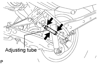
Inspect the nuts and adjusting tube for looseness visually and by hand.*1
-
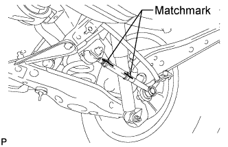
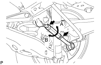
Place matchmarks on the arm, nuts and adjusting tube as shown in the illustration.*2
-
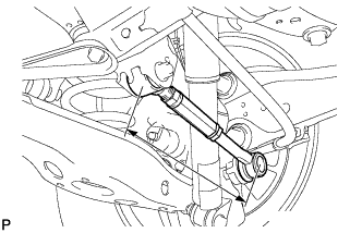
Using SST, apply the specified torque to the adjusting tube in the following order and check that the matchmarks are still aligned: 1) extend direction, 2) contract direction.*3
- SST
- 09612-24014 ( 09617-24011 )
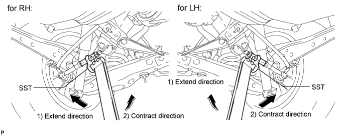
- Torque:
- without SST
- 20 N*m { 204 kgf*cm, 15 ft.*lbf }
- with SST
- 17 N*m { 173 kgf*cm, 13 ft.*lbf }
Note
Use the formula to calculate special torque values for situations where SST is combined with a torque wrench Click here.
Tech Tips
Use a torque wrench with a fulcrum length of 30 cm (11.81 in.).
-
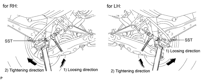
Hold the adjusting tube in place and, using SST, apply the specified torque to the nut on the ball joint side in the following order and check that the matchmarks are still aligned: 1) loosing direction, 2) tightening direction.*4
- SST
- 09612-24014 ( 09617-24011 )
- Torque:
- without SST
- 20 N*m { 204 kgf*cm, 15 ft.*lbf }
- with SST
- 17 N*m { 173 kgf*cm, 13 ft.*lbf }
Note
Use the formula to calculate special torque values for situations where SST is combined with a torque wrench Click here.
Tech Tips
Use a torque wrench with a fulcrum length of 30 cm (11.81 in.).
-
If the adjusting tube or either nut is determined to be loose when performing steps *1 to *4, replace the rear No. 1 suspension arm.
-
-
Measure the length of the left and right rear No. 1 suspension arms.
Standard difference 1.0 mm (0.0394 in.) or less -
Loosen the 2 lock nuts of the adjusting tube.
Note
If either nut is abnormally tight when loosening it (90 N*m (918 kgf*cm, 66 ft.*lbf) or more), or if either nut does not rotate smoothly by hand after loosening it, replace the rear No. 1 suspension arm.
Tech Tips
Loosen the 2 lock nuts of the adjusting tube on the other side using the same procedure.
-
If the difference between the length of the left and right rear No. 1 suspension arms is not within the specification, adjust the value to within the specification using the method below.
-
If the toe-in value deviates towards the inside, turn the adjusting tube of the shorter No. 1 suspension arm assembly in the direction which increases arm length until the difference between the left and right suspension arms is within the specification.
-
If the toe-in value deviates towards the outside, turn the adjusting tube of the longer No. 1 suspension arm assembly in the direction which decreases arm length until the difference between the left and right suspension arms is within the specification.
-
Measure the toe-in again.
-
-
Turn the left and right adjusting tubes in the same direction by the same amount to adjust the toe-in.
Adjustment Value except Rough Road Package 1 Item Specified Condition Toe-in B - A: 1.8 +/-2 mm (0.07 +/-0.08 in.) Adjustment Value for Rough Road Package 1 Item Specified Condition Toe-in B - A: 0.3 +/-2 mm (0.01 +/-0.08 in.) Tech Tips
-
When the adjusting tube of the rear No. 1 suspension arm assembly LH is turned one revolution in the direction of A in the illustration, the toe-in changes to the inside by approximately 3.7 mm (0.146 in.).
-
When the adjusting tube of the rear No. 1 suspension arm assembly LH is turned one revolution in the direction of B in the illustration, the toe-in changes to the outside by approximately 3.7 mm (0.146 in.).
-
-
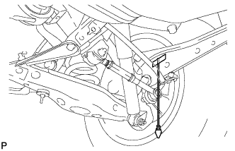
Attach a string and weight to the vehicle as shown in the illustration.
-
Place the vehicle on a level surface, and then check that the string and weight are perpendicular to the vehicle body.
-
Hold the adjusting tube in place and, using SST, tighten the nut on the ball joint side.*5
- SST
- 09612-24014 ( 09617-24011 )
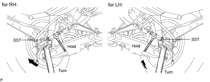
- Torque:
- without SST
- 20 N*m { 204 kgf*cm, 15 ft.*lbf }
- with SST
- 17 N*m { 173 kgf*cm, 13 ft.*lbf }
Note
Use the formula to calculate special torque values for situations where SST is combined with a torque wrench Click here.
Tech Tips
Use a torque wrench with a fulcrum length of 30 cm (11.81 in.).
-
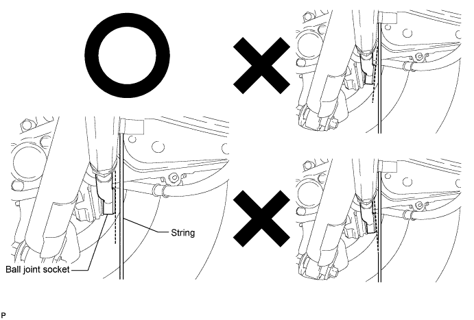
Turn the adjusting tube so that the ball joint socket is parallel to the string as shown in the illustration.*6
-
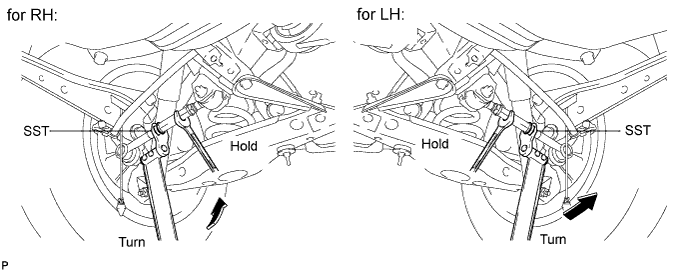
Hold the adjusting tube in place and, using SST, loosen the nut on the ball joint side.*7
- SST
- 09612-24014 ( 09617-24011 )
-
Hold the adjusting tube in place and, using SST, tighten the nut on the rubber bush side and nut on the ball joint side in the following order: 1) rubber bush side, 2) ball joint side, 3) rubber bush side.*8
- SST
- 09612-24014 ( 09617-24011 )
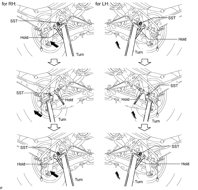
- Torque:
- without SST
- 56 N*m { 571 kgf*cm, 41 ft.*lbf }
- with SST
- 48 N*m { 489 kgf*cm, 35 ft.*lbf }
Note
Use the formula to calculate special torque values for situations where SST is combined with a torque wrench Click here.
Tech Tips
Use a torque wrench with a fulcrum length of 30 cm (11.81 in.).
-
Final check, hold the adjusting tube in place and, using SST, tighten the nut on the rubber bush side and nut on the ball joint side in the following order: 1) rubber bush side, 2) ball joint side, 3) rubber bush side.*9
- SST
- 09612-24014 ( 09617-24011 )
- Torque:
- without SST
- 45 N*m { 459 kgf*cm, 33 ft.*lbf }
- with SST
- 38 N*m { 387 kgf*cm, 28 ft.*lbf }
Note
Use the formula to calculate special torque values for situations where SST is combined with a torque wrench Click here.
Tech Tips
Use a torque wrench with a fulcrum length of 30 cm (11.81 in.).
-
Check that the ball joint socket is parallel to the string.
Note
If the ball joint socket is at an angle of 5° or more with respect to the string, perform steps *5 to *9 again.
-
Remove the string and weight from the vehicle.
-
-
INSPECT CAMBER
Text in Illustration *1 Gauge
-
Install a camber-caster-kingpin gauge or set the vehicle on a wheel alignment tester.
-
Inspect the camber.
Standard Camber Inclination (Unloaded Vehicle) Item Camber Inclination except Rough Road Package 1 Camber
Left-right error
-1°00' +/-45' (-1.00°+/-0.75°)
45' (0.75°) or less
for Rough Road Package 1 Camber
Left-right error
-0°48' +/-45' (-0.8°+/-0.75°)
45' (0.75°) or less
If the measured value is not within the specified range, inspect the suspension parts for damage and wear. Replace parts as necessary as the camber cannot be properly adjusted with any damaged or worn parts.
-