REAR AXLE HUB INSTALLATION

-
INSTALL REAR AXLE HUB AND BEARING ASSEMBLY LH
-
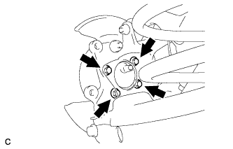
Install the rear axle hub and bearing assembly with the 4 bolts.
- Torque:
- 90 N*m { 918 kgf*cm, 66 ft.*lbf }
-
-
CONNECT SKID CONTROL SENSOR WIRE
Note
To prevent interference with other parts, do not twist the painted line areas of the sensor wire when installing it.
-

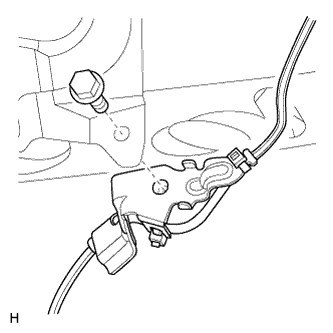
Connect the skid control sensor wire connector to the skid control sensor.
-
Attach the sensor clamp.
Note
Do not twist the sensor wire when installing the clamp.
-
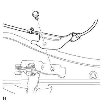
Install the sensor clamp with the bolt.
- Torque:
- 8.5 N*m { 87 kgf*cm, 75 in.*lbf }
Note
Do not twist the sensor wire when installing the clamp.
-
Install the sensor clamp with the bolt.
- Torque:
- 8.5 N*m { 87 kgf*cm, 75 in.*lbf }
Note
Do not twist the sensor wire when installing the clamp.
-
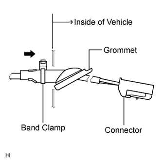
Insert the connector and grommet into the inside of the vehicle through the hole in the wheel house.
Note
Make sure the band clamp remains on the outside of the vehicle.
-
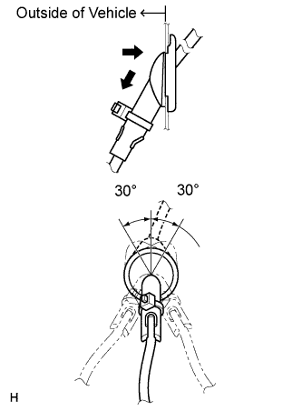
Hold the grommet and pull it toward the outside of the vehicle. Then fix the grommet in place so that it is not tilted.
Note
-
When pulling out the grommet, do not grip the sensor wire.
-
Fix the grommet in place within the range shown in the illustration.
-
-
Connect the skid control sensor wire connector to the vehicle side connector on the rear floor.
-
-
INSPECT REAR AXLE HUB BEARING LOOSENESS
-
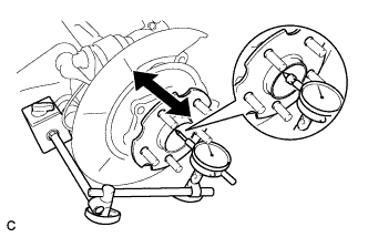
Using a dial indicator, check for looseness near the center of the axle hub.
Maximum looseness 0.05 mm (0.00197 in.) Note
Make sure that the dial indicator is set perpendicular to the measurement surface.
Tech Tips
If the looseness more than the maximum, replace the axle hub assembly.
-
-
INSPECT REAR AXLE HUB RUNOUT
-
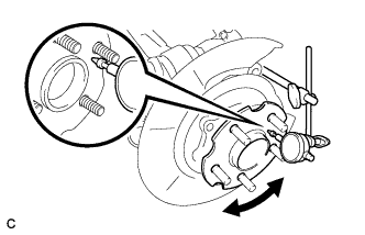
Using a dial indicator, check for runout on the surface of the axle hub inside the rear axle hub bolts.
Maximum runout 0.08 mm (0.00314 in.) Note
-
Make sure that the dial indicator is set perpendicular to the measurement surface.
-
Make sure to set the tip of the dial indicator inside the rear axle hub bolts.
If the runout more than the maximum, replace the rear axle hub and bearing assembly.
-
-
-
INSTALL REAR DISC
-
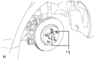
Text in Illustration *1 Matchmark Align the matchmarks of the disc and axle hub and install the disc.
Note
When replacing the disc with a new one, select the installation position where the rear disc has minimal runout.
-
-
INSTALL REAR DISC BRAKE CYLINDER ASSEMBLY LH
-
Install the rear disc brake cylinder assembly Click here.
-
-
INSPECT REAR WHEEL ALIGNMENT
-
Inspect the rear wheel alignment Click here.
-
-
CHECK SPEED SENSOR SIGNAL
-
Inspect the speed sensor signal Click here.
-