OUTPUT SHAFT REASSEMBLY

-
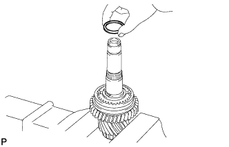
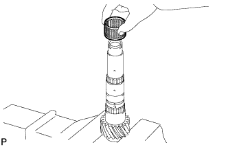
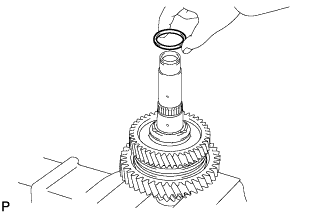
INSTALL NEEDLE ROLLER BEARING
-
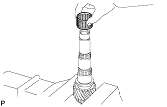
Coat the needle roller bearing with gear oil, and install it into the No. 2 output shaft.
-
-
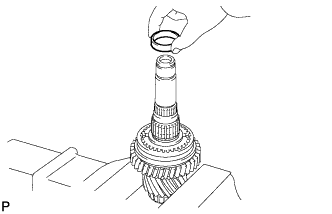
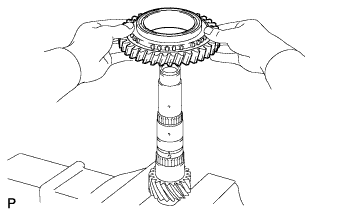
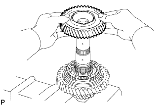
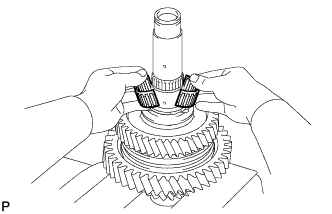
INSTALL REVERSE DRIVEN GEAR
-
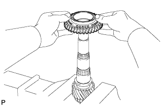
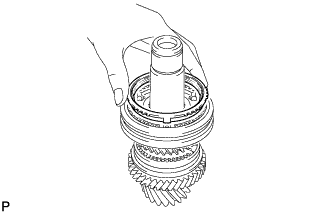
Coat the reverse driven gear with gear oil, and install it into the No. 2 output shaft.
-
-
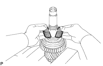
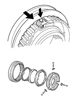
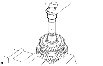
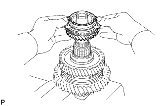
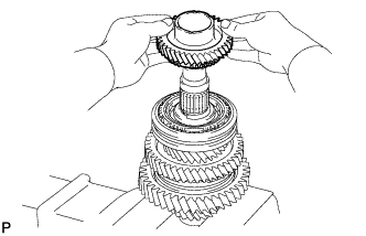
INSTALL NO. 4 TRANSMISSION CLUTCH HUB
-
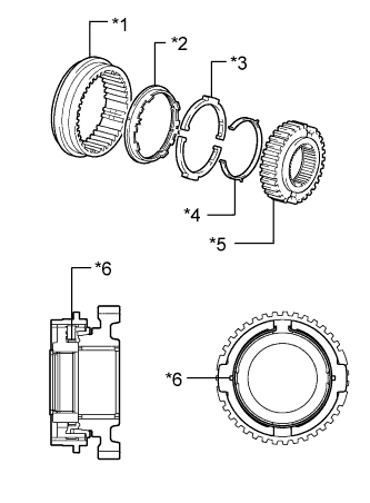
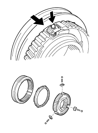
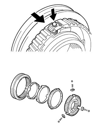
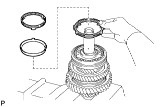
Text in Illustration *1 Hub Sleeve *2 Reverse Driven Gear Synchronizer Ring *3 Shifting Key *4 Key Spring *5 Clutch Hub *6 Claw Install the key spring and 2 shifting keys to the clutch hub.
Tech Tips
-
Install the shifting key with the grooves on the clutch hub side.
-
Install the key spring with the claw on the clutch hub side.
-
Refer to the illustration when installing the key spring and shifting keys.
-
-
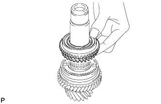
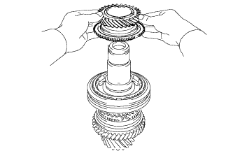
Install the hub sleeve to the reverse driven gear as shown in the illustration.
-
Coat the No. 4 transmission clutch hub with gear oil, and install it into the No. 2 output shaft.
-
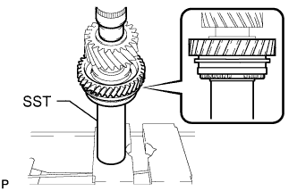
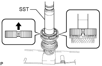
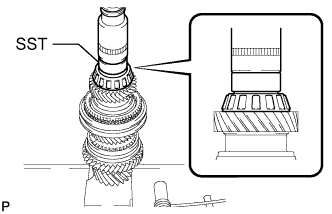
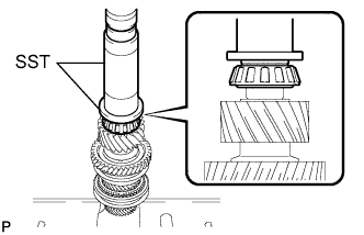
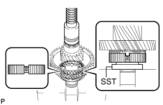
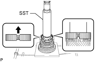
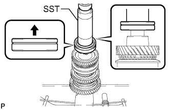
Using SST and a press, press in the reverse gear and No. 4 transmission clutch hub into the No. 2 output shaft.
- SST
- 09308-14010
Note
After installation, make sure that the gear and synchronizer ring move smoothly.
Tech Tips
Make sure that the protruding part on the synchronizer ring is fitted into the groove of the clutch hub.
-
-
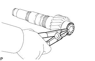
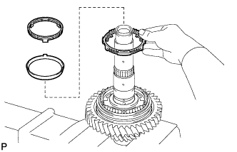
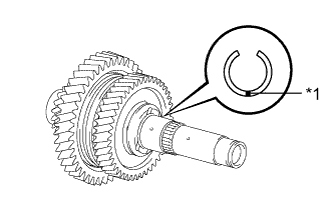
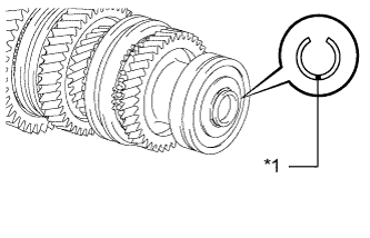
INSTALL SHAFT SNAP RING
-
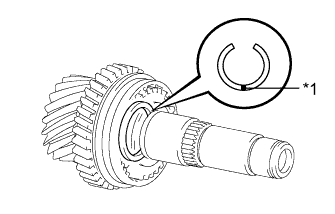
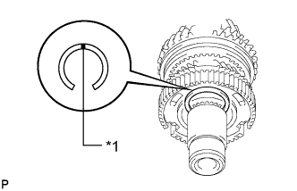
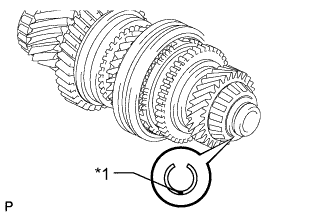
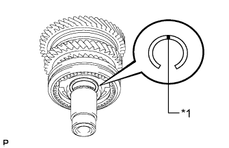
Text in Illustration *1 Mark Select a new snap ring, using the table below, that makes the thrust clearance of the No. 4 transmission clutch hub less than 0.1 mm (0.00394 in.).
Standard shaft snap ring thickness Mark Specified Condition Mark Specified Condition A 2.25 to 2.30 mm (0.0886 to 0.0906 in.) E 2.45 to 2.50 mm (0.0965 to 0.0984 in.) B 2.30 to 2.35 mm (0.0906 to 0.0925 in.) F 2.50 to 2.55 mm (0.0984 to 0.100 in.) C 2.35 to 2.40 mm (0.0925 to 0.0945 in.) G 2.55 to 2.60 mm (0.100 to 0.102 in.) D 2.40 to 2.45 mm (0.0945 to 0.0965 in.) H 2.60 to 2.65 mm (0.102 to 0.104 in.) -
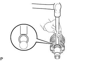
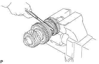
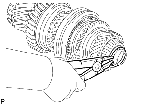
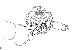
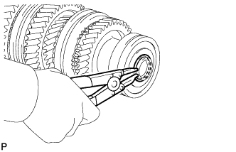
Using a brass bar and hammer, tap the snap ring onto the No. 2 output shaft.
-
-
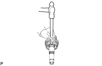
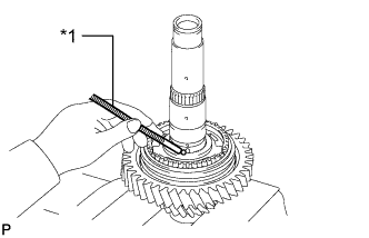
INSPECT REVERSE DRIVEN GEAR THRUST CLEARANCE
-
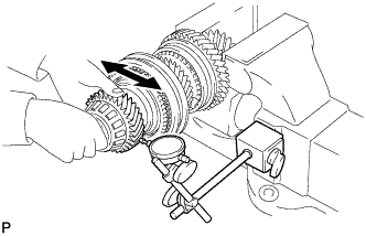
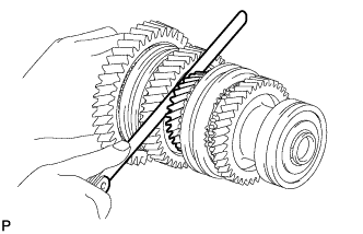
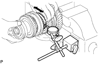
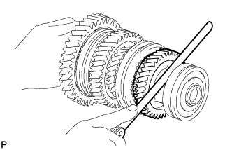
Using a feeler gauge, measure the reverse driven gear thrust clearance.
Standard clearance 0.11 to 0.34 mm (0.00434 to 0.0133 in.) Maximum clearance 0.34 mm (0.0133 in.) If the clearance is more than the maximum, replace the reverse driven gear, needle roller bearing or output shaft. Replace the part or parts determined to be the most likely cause of the problem.
-
-
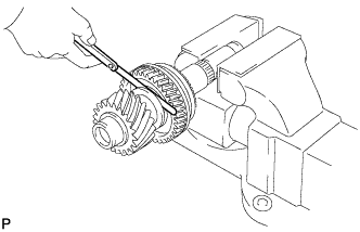
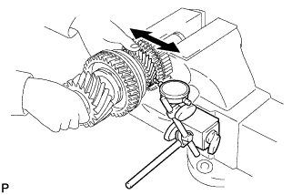
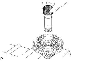
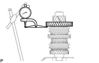
INSPECT REVERSE DRIVEN GEAR RADIAL CLEARANCE
-
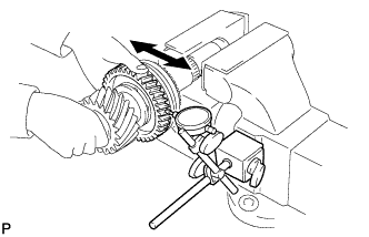
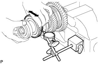
Using a dial indicator, measure the reverse driven gear radial clearance.
Standard clearance 0.015 to 0.068 mm (0.000591 to 0.00267 in.) Maximum clearance 0.068 mm (0.00267 in.) If the clearance is more than the maximum, replace the reverse driven gear, needle roller bearing or output shaft. Replace the part or parts determined to be the most likely cause of the problem.
-
-
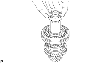
INSTALL 5TH DRIVEN GEAR
-
Install the output shaft spacer into the No. 2 output shaft.
-
Coat the 2 pieces of the needle roller bearing with gear oil, and install them into the No. 2 output shaft.
-
Install the output shaft spacer into the No. 2 output shaft.
-
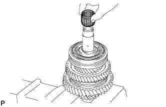
Coat the 5th driven gear with gear oil, and install it into the No. 2 output shaft.
-
-
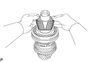
INSTALL NO. 3 TRANSMISSION CLUTCH HUB
-
Apply of gear oil to the sleeve and hub.
-
Install the hub sleeve to the clutch hub.
-
Install the 3 shifting keys to the clutch hub.
-
Install the 3 shifting key springs to the clutch hub.
-
Place the 3 balls in the holes of the shifting keys, and install the hub sleeve while pushing in the balls.
Note
Take care to prevent the balls from scattering.
-
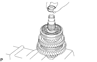
Coat the 5th driven gear synchronizer ring with gear oil, and install it to the 5th driven gear.
-
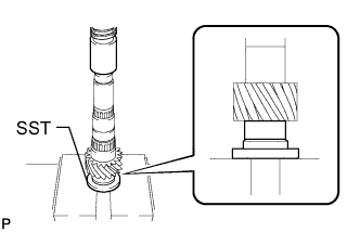
Using SST and a press, press in the No. 3 transmission clutch hub to the No. 2 output shaft.
- SST
- 09308-14010
Tech Tips
Make sure that the protruding part on the synchronizer ring is fitted into the groove of the clutch hub.
Note
After installation, make sure that the gear and synchronizer ring move smoothly.
-
-
INSTALL SHAFT SNAP RING
-
Text in Illustration *1 Mark Select a new snap ring, using the table below, that makes the thrust clearance of the No. 3 transmission clutch hub less than 0.1 mm (0.00394 in.).
Standard shaft snap ring thickness Mark Specified Condition Mark Specified Condition 1 2.25 to 2.30 mm (0.0886 to 0.0906 in.) 4 2.40 to 2.45 mm (0.0945 to 0.0965 in.) 2 2.30 to 2.35 mm (0.0906 to 0.0925 in.) 5 2.45 to 2.50 mm (0.0965 to 0.0984 in.) 3 2.35 to 2.40 mm (0.0925 to 0.0945 in.) 6 2.50 to 2.55 mm (0.0984 to 0.100 in.) -
Using a brass bar and hammer, tap the snap ring onto the No. 2 output shaft.
-
-
INSPECT 5TH DRIVEN GEAR THRUST CLEARANCE
-
Using a feeler gauge, measure the 5th driven gear thrust clearance.
Standard clearance 0.10 to 0.55 mm (0.00394 to 0.0216 in.) Maximum clearance 0.55 mm (0.0216 in.) If the clearance is more than the maximum, replace the 5th driven gear, needle roller bearing or output shaft. Replace the part or parts determined to be the most likely cause of the problem.
-
-
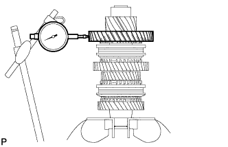
INSPECT 5TH DRIVEN GEAR RADIAL CLEARANCE
-
Using a dial indicator, measure the 5th driven gear radial clearance.
Standard clearance 0.015 to 0.066 mm (0.000591 to 0.00259 in.) Maximum clearance 0.066 mm (0.00259 in.) If the clearance is more than the maximum, replace the 5th driven gear, needle roller bearing or output shaft. Replace the part or parts determined to be the most likely cause of the problem.
-
-
INSTALL 6TH DRIVEN GEAR
-
Install the spacer into the No. 2 output shaft.
-
Coat the 2 pieces of the needle roller bearing with gear oil, and install them into the No. 2 output shaft.
-
Coat the 6th gear synchronizer ring with gear oil, and install it into the transmission clutch hub.
-
Coat the 6th driven gear with gear oil, and install it into the No. 2 output shaft.
-
-
INSTALL NO. 2 OUTPUT SHAFT REAR BEARING
-
Using SST and a press, press in the No. 2 output shaft rear bearing to the No. 2 output shaft.
- SST
- 09710-04071
Note
After installation, make sure that the gear and synchronizer ring move smoothly.
-
-
INSTALL NO. 2 OUTPUT SHAFT BEARING SNAP RING
-
Text in Illustration *1 Mark Select a new snap ring, using the table below, that makes the thrust clearance of the 6th gear less than 0.1 mm (0.00394 in.).
Standard No. 2 output shaft bearing snap ring thickness Mark Specified Condition Mark Specified Condition B 1.85 to 1.90 mm (0.0728 to 0.0748 in.) 0 2.05 to 2.10 mm (0.0807 to 0.0827 in.) C 1.90 to 1.95 mm (0.0748 to 0.0768 in.) 1 2.10 to 2.15 mm (0.0827 to 0.0846 in.) D 1.95 to 2.00 mm (0.0768 to 0.0787 in.) 2 2.15 to 2.20 mm (0.0846 to 0.0866 in.) E 2.00 to 2.05 mm (0.0787 to 0.0807 in.) - - -
Using a snap ring expander, install the snap ring onto the No. 2 output shaft.
-
-
INSPECT 6TH DRIVEN GEAR THRUST CLEARANCE
-

Using a feeler gauge, measure the 6th driven gear thrust clearance.
Standard clearance 0.10 to 0.55 mm (0.00394 to 0.0216 in.) Maximum clearance 0.55 mm (0.0216 in.) If the clearance is more than the maximum, replace the 6th driven gear, needle roller bearing or output shaft. Replace the part or parts determined to be the most likely cause of the problem.
-
-
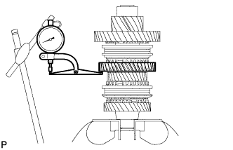
INSPECT 6TH DRIVEN GEAR RADIAL CLEARANCE
-
Using a dial indicator, measure the 6th driven gear radial clearance.
Standard clearance 0.015 to 0.066 mm (0.000591 to 0.00259 in.) Maximum clearance 0.066 mm (0.00259 in.) If the clearance is more than the maximum, replace the 6th driven gear, needle roller bearing or output shaft. Replace the part or parts determined to be the most likely cause of the problem.
-
-
INSTALL NO. 2 OUTPUT SHAFT FRONT BEARING
-
Using SST and a press, press in the No. 2 output shaft front bearing into the No. 2 output shaft.
- SST
- 09309-37010
- 09506-30012
-
-
INSTALL OUTPUT SHAFT FRONT BEARING
-
Using SST and a press, press in the output shaft front bearing into the No. 1 output shaft.
- SST
- 09309-14040
-
-
INSTALL OUTPUT SHAFT FRONT BEARING SHAFT SNAP RING
-
Using a snap ring expander, install a new snap ring into the No. 1 output shaft.
-
-
INSTALL 1ST DRIVEN GEAR
-
Coat the needle roller bearing with gear oil, and install it into the No. 1 output shaft.
-
Coat the 1st driven gear with gear oil, and install it into the No. 1 output shaft.
-
-
INSTALL NO. 1 TRANSMISSION CLUTCH HUB
-
Apply of gear oil to the sleeve and hub.
-
Install the hub sleeve to the clutch hub.
-
Install the 3 shifting keys to the clutch hub.
-
Install the 3 shifting key springs to the clutch hub.
-
Place the 3 balls in the holes of the shifting keys, and install the hub sleeve while pushing in the balls.
Note
Take care to prevent the balls from scattering.
-
Coat the 3 pieces of the 1st driven gear synchronizer ring set with gear oil, and install them to the 1st driven gear.
-
Using SST and a press, press in the No. 1 transmission hub sleeve to the No. 1 output shaft.
- SST
- 09726-40010
Note
After installation, make sure that the gear and synchronizer ring move smoothly.
Tech Tips
Make sure that the protruding part on the synchronizer ring is fitted into the groove of the clutch hub.
-
-
INSTALL 2ND DRIVEN GEAR SYNCHRONIZER RING SET
-
Coat the 3 pieces of the 2nd driven gear synchronizer ring set with gear oil, and install them to the No. 1 output shaft.
-
-
INSTALL SYNCHROMESH SHIFTING KEY BALL
-
Text in Illustration *1 Magnet Hand Install the key ball onto the No. 1 output shaft.
-
-
INSTALL NEEDLE ROLLER BEARING
-
Coat the needle roller bearing with gear oil, and install it into the No. 1 output shaft.
-
-
INSTALL 2ND DRIVEN GEAR
-
Coat the 2nd driven gear with gear oil, and install it into the No. 1 output shaft.
-
-
INSTALL INNER 2ND DRIVEN GEAR BEARING RACE
-
Align the groove of the inner 2nd driven gear bearing race with the ball, and install it.
-
-
INSTALL OUTPUT SHAFT BEARING SHAFT SNAP RING
-
Text in Illustration *1 Mark Select a new snap ring, using the table below, that makes the thrust clearance of the 2nd gear less than 0.1 mm (0.00394 in.).
Standard output shaft bearing shaft snap ring thickness Mark Specified Condition Mark Specified Condition A 2.25 to 2.30 mm (0.0886 to 0.0906 in.) E 2.45 to 2.50 mm (0.0965 to 0.0984 in.) B 2.30 to 2.35 mm (0.0906 to 0.0925 in.) F 2.50 to 2.55 mm (0.0984 to 0.100 in.) C 2.35 to 2.40 mm (0.0925 to 0.0945 in.) G 2.55 to 2.60 mm (0.100 to 0.102 in.) D 2.40 to 2.45 mm (0.0945 to 0.0965 in.) H 2.60 to 2.65 mm (0.102 to 0.104 in.) -
Using a snap ring expander, install the snap ring into the No. 1 output shaft.
Note
Do not damage the journal surface of the No. 1 output shaft.
-
-
INSPECT 1ST DRIVEN GEAR THRUST CLEARANCE
-
Using a dial indicator, measure the 1st driven gear thrust clearance.
Standard clearance 0.10 to 0.35 mm (0.00394 to 0.0137 in.) Maximum clearance 0.35 mm (0.0137 in.) If the clearance is more than the maximum, replace the 1st driven gear, needle roller bearing or output shaft. Replace the part or parts determined to be the most likely cause of the problem.
-
-
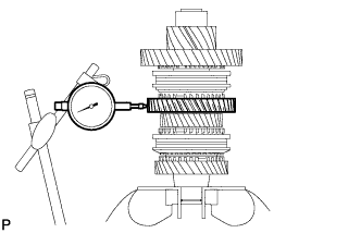
INSPECT 1ST DRIVEN GEAR RADIAL CLEARANCE
-
Using a dial indicator, measure the 1st driven gear radial clearance.
Standard clearance 0.015 to 0.068 mm (0.000591 to 0.00267 in.) Maximum clearance 0.068 mm (0.00267 in.) If the clearance is more than the maximum, replace the 1st driven gear, needle roller bearing or output shaft. Replace the part or parts determined to be the most likely cause of the problem.
-
-
INSPECT 2ND DRIVEN GEAR THRUST CLEARANCE
-
Using a dial indicator, measure the 2nd driven gear thrust clearance.
Standard clearance 0.11 to 0.46 mm (0.00434 to 0.0181 in.) Maximum clearance 0.46 mm (0.0181 in.) If the clearance is more than the maximum, replace the 2nd driven gear, needle roller bearing or output shaft. Replace the part or parts determined to be the most likely cause of the problem.
-
-
INSPECT 2ND DRIVEN GEAR RADIAL CLEARANCE
-
Using a dial indicator, measure the 2nd driven gear radial clearance.
Standard clearance 0.015 to 0.048 mm (0.000591 to 0.00188 in.) Maximum clearance 0.048 mm (0.00188 in.) If the clearance is more than the maximum, replace the 2nd driven gear, needle roller bearing or output shaft. Replace the part or parts determined to be the most likely cause of the problem.
-
-
INSTALL 4TH DRIVEN GEAR
-
Install the spacer into the No. 1 output shaft.
-
Coat the 2 pieces of the 4th driven gear needle roller bearing with gear oil, and install them into the No. 1 output shaft.
-
Coat the 4th driven gear with gear oil, and install it into the No. 1 output shaft.
-
-
INSTALL NO. 2 TRANSMISSION CLUTCH HUB
-
Apply of gear oil to the sleeve and hub.
-
Install the hub sleeve to the clutch hub.
-
Install the 3 shifting keys to the clutch hub.
-
Install the 3 shifting key springs to the clutch hub.
-
Place the 3 balls in the holes of the shifting keys, and install the hub sleeve while pushing in the balls.
Note
Take care to prevent the balls from scattering.
-
Coat the 3 pieces of the 4th driven gear synchronizer ring set with gear oil, and install them into the 4th driven gear.
-
Using SST and a press, press in the No. 2 transmission hub sleeve to the No. 1 output shaft.
- SST
- 09309-14010
Tech Tips
Make sure that the protruding part on the synchronizer ring is fitted into the groove of the clutch hub.
Note
After installation, make sure that the gear and synchronizer ring move smoothly.
-
-
INSTALL SHAFT SNAP RING
-
Text in Illustration *1 Mark Select a new snap ring, using the table below, that makes the thrust clearance of the No. 2 transmission clutch hub less than 0.1 mm (0.00394 in.).
Standard shaft snap ring thickness Mark Specified Condition Mark Specified Condition 1 2.25 to 2.30 mm (0.0886 to 0.0906 in.) 4 2.40 to 2.45 mm (0.0945 to 0.0965 in.) 2 2.30 to 2.35 mm (0.0906 to 0.0925 in.) 5 2.45 to 2.50 mm (0.0965 to 0.0984 in.) 3 2.35 to 2.40 mm (0.0925 to 0.0945 in.) 6 2.50 to 2.55 mm (0.0984 to 0.100 in.) -
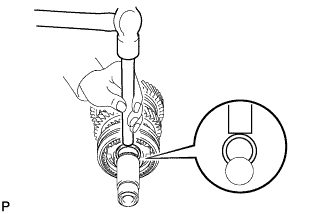
Using a brass bar and hammer, tap the snap ring into the No. 1 output shaft.
-
-
INSPECT 4TH DRIVEN GEAR THRUST CLEARANCE
-
Using a feeler gauge, measure the 4th driven gear thrust clearance.
Standard clearance 0.10 to 0.65 mm (0.00394 to 0.0255 in.) Maximum clearance 0.65 mm (0.0255 in.) If the clearance is more than the maximum, replace the 4th driven gear, needle roller bearing or output shaft. Replace the part or parts determined to be the most likely cause of the problem.
-
-
INSPECT 4TH DRIVEN GEAR RADIAL CLEARANCE
-
Using a dial indicator, measure the 4th driven gear radial clearance.
Standard clearance 0.015 to 0.066 mm (0.000591 to 0.00259 in.) Maximum clearance 0.066 mm (0.00259 in.) If the clearance is more than the maximum, replace the 4th driven gear, needle roller bearing or output shaft. Replace the part or parts determined to be the most likely cause of the problem.
-
-
INSTALL 3RD DRIVEN GEAR
-
Coat the 3rd driven gear synchronizer ring set with gear oil, and install it into the No. 1 output shaft.
-
Coat the needle roller bearing with gear oil, and install it into the No. 1 output shaft.
-
Install the spacer into the No. 1 output shaft.
-
Coat the 3rd driven gear with gear oil, and install it into the No. 1 output shaft.
-
-
INSTALL OUTPUT SHAFT FRONT BEARING
-
Using SST and a press, press in the output shaft front bearing into the No. 1 output shaft.
- SST
- 09308-14010
Tech Tips
When pressing in the bearing, apply force to only the inner race. Do not apply force to the seal.
Note
After installation, make sure that the gear and synchronizer ring move smoothly.
-
-
INSTALL OUTPUT SHAFT BEARING SHAFT SNAP RING
-
Standard output shaft bearing snap ring thickness Mark Specified Condition Mark Specified Condition B 1.85 to 1.90 mm (0.0728 to 0.0748 in.) 0 2.05 to 2.10 mm (0.0807 to 0.0827 in.) C 1.90 to 1.95 mm (0.0748 to 0.0768 in.) 1 2.10 to 2.15 mm (0.0827 to 0.0846 in.) D 1.95 to 2.00 mm (0.0768 to 0.0787 in.) 2 2.15 to 2.20 mm (0.0846 to 0.0866 in.) E 2.00 to 2.05 mm (0.0787 to 0.0807 in.) - - Text in Illustration *1 Mark Select a new snap ring, using the table below, that makes the thrust clearance of the output shaft bearing less than 0.1 mm (0.00394 in.).
Standard output shaft bearing snap ring thickness Mark Specified Condition Mark Specified Condition B 1.85 to 1.90 mm (0.0728 to 0.0748 in.) 0 2.05 to 2.10 mm (0.0807 to 0.0827 in.) C 1.90 to 1.95 mm (0.0748 to 0.0768 in.) 1 2.10 to 2.15 mm (0.0827 to 0.0846 in.) D 1.95 to 2.00 mm (0.0768 to 0.0787 in.) 2 2.15 to 2.20 mm (0.0846 to 0.0866 in.) E 2.00 to 2.05 mm (0.0787 to 0.0807 in.) - - Text in Illustration *1 Mark -
Text in Illustration *1 Mark Using a snap ring expander, install the snap ring onto the No. 1 output shaft.
-
-
INSPECT 3RD DRIVEN GEAR THRUST CLEARANCE
-
Using a feeler gauge, measure the 3rd driven gear thrust clearance.
Standard clearance 0.11 to 0.54 mm (0.00434 to 0.0212 in.) Maximum clearance 0.54 mm (0.0212 in.) If the clearance is more than the maximum, replace the 3rd driven gear, needle roller bearing or output shaft. Replace the part or parts determined to be the most likely cause of the problem.
-
-
INSPECT 3RD DRIVEN GEAR RADIAL CLEARANCE
-
Using a dial indicator, measure the 3rd driven gear radial clearance.
Standard clearance 0.015 to 0.066 mm (0.000591 to 0.00259 in.) Maximum clearance 0.066 mm (0.00259 in.) If the clearance is more than the maximum, replace the 3rd driven gear, needle roller bearing or output shaft. Replace the part or parts determined to be the most likely cause of the problem.
-