CLUTCH RELEASE CYLINDER INSTALLATION

-
INSTALL CLUTCH RELEASE CYLINDER KIT
-
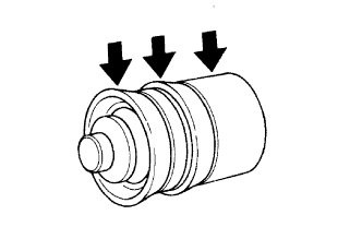
Coat a new piston with lithium soap base glycol grease as shown in the illustration.
-
Install the piston and a new spring to the cylinder body.
Note
Do not damage the inside of the cylinder body.
Tech Tips
Install the smaller end of the spring to the piston.
-
Install a new boot to the push rod.
-
Install the push rod together with the boot to the cylinder body.
-
-
TEMPORARILY INSTALL RELEASE CYLINDER BLEEDER PLUG
-
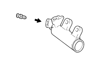
Install the release cylinder bleeder plug to the cylinder body.
- Torque:
- 8.4 N*m { 86 kgf*cm, 74 in.*lbf }
-
Install the bleeder plug cap to the bleeder plug.
-
-
INSTALL CLUTCH RELEASE CYLINDER ASSEMBLY
-
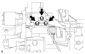
Install the clutch release cylinder and No. 1 clutch tube bracket with the 3 bolts.
- Torque:
- 12 N*m { 122 kgf*cm, 9 ft.*lbf }
-
-
CONNECT CLUTCH RELEASE CYLINDER TO ACCUMULATOR TUBE
-
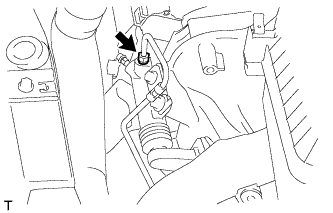
Using a union nut wrench, connect the clutch release cylinder to accumulator tube.
- Torque:
- 15 N*m { 155 kgf*cm, 11 ft.*lbf }
Note
Use the formula to calculate special torque values for situations where a union nut wrench is combined with a torque wrench Click here.
-
-
INSTALL BATTERY TRAY
-
INSTALL BATTERY
-
INSTALL BATTERY CLAMP SUB-ASSEMBLY
-
Attach the hook of the battery clamp to the battery carrier.
-
Partially tighten the nut and temporarily install the bolt.
-
Adjust the battery clamp position.
-
Tighten the nut and bolt.
- Torque:
- for bolt
- 17 N*m { 168 kgf*cm, 12 ft.*lbf }
- for nut
- 3.5 N*m { 36 kgf*cm, 31 in.*lbf }
-
-
INSTALL RADIATOR SUPPORT OPENING COVER
-
Install the radiator support opening cover with the 7 clips.
-
-
CONNECT CABLE TO POSITIVE BATTERY TERMINAL
-
CONNECT CABLE TO NEGATIVE BATTERY TERMINAL
Note
When disconnecting the cable, some systems need to be initialized after the cable is reconnected Click here.
-
BLEED CLUTCH LINE
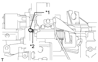
Text in Illustration *1 Bleeder Plug Cap *2 Bleeder Plug
-
Remove the bleeder plug cap.
-
Connect a vinyl tube to the bleeder plug.
-
Depress the clutch pedal several times, and then loosen the bleeder plug while the pedal is depressed.
-
When fluid no longer comes out, tighten the bleeder plug, and then release the clutch pedal.
-
Repeat the previous 2 steps until all the air in the fluid is completely bled.
-
Tighten the bleeder plug.
- Torque:
- 8.4 N*m { 86 kgf*cm, 74 in.*lbf }
-
Install the bleeder plug cap.
-
Check that all the air has been bled from the clutch line.
-
-
INSPECT FLUID LEVEL
-
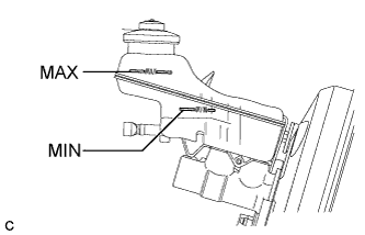
Check the fluid level.
If the brake fluid level is lower than the MIN line, check for leaks and inspect the disc brake pads. If necessary, refill the reservoir with brake fluid to the MAX line after repair or replacement.
Brake Fluid SAE J1704 or FMVSS No. 116 DOT 4
-
-
INSPECT FOR FLUID LEAK
Tech Tips
Check for leaks in the clutch system.