TRANSMISSION CONTROL CABLE INSTALLATION

-
INSTALL TRANSMISSION CONTROL CABLE ASSEMBLY
-
Install the control cable assembly through the floor hole.
-
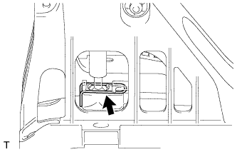
Attach the 2 claws to connect the shift control cable and select control cable to the floor shift lever assembly.
-
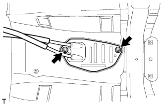
Attach the grommet of the control cable assembly with the 2 nuts.
- Torque:
- 5.0 N*m { 51 kgf*cm, 44 in.*lbf }
-
Connect the end of the shift control cable to the shift lever assembly and install the clip.
-
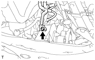
Attach the bracket of the control cable assembly with the bolt.
- Torque:
- 5.0 N*m { 51 kgf*cm, 44 in.*lbf }
-
Connect the 2 cables to the control cable bracket with 2 new clips.
-
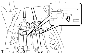
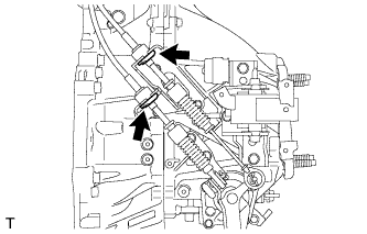
Connect the 2 cables to the transaxle and install the 2 clips.
-
Release the lock of the cable length adjustment structure of the select cable.
-
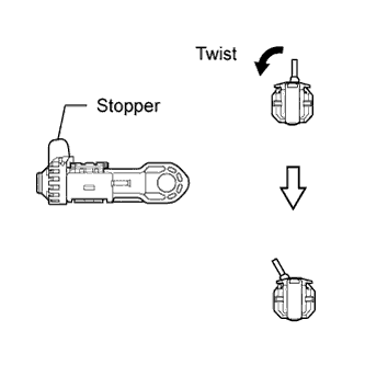
Twist the stopper.
-
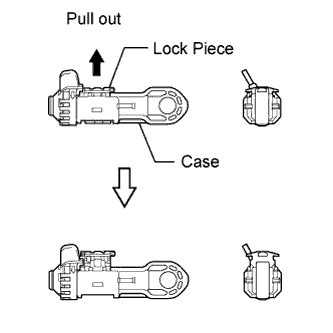
Pull the lock piece outward from the case to release the lock.
-
-
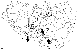
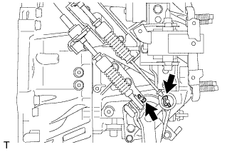
Pressing the shift and select lever shaft (*1) and pin (*2), push in pin (*3) and check that the shift and select lever shaft is secured at the 1st-2nd gear selected position (the shaft comes to a stop at the position 8 mm (0.315 in.) below the N position).
-
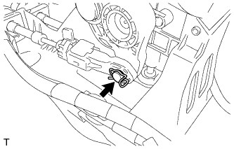
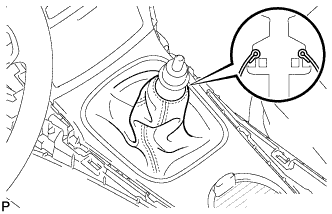
Connect the end of the select control cable to the shift lever assembly and install the clip.
Note
-
Make sure the lock piece of the select control cable is facing upward when the select control cable is connected.
-
Make sure the clip is inserted in the direction shown in the illustration.
-
-
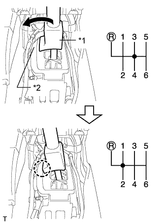
Text in Illustration *1 Slider *2 Inhibitor Wall Push the slider against the inhibitor wall.
Note
-
Do not pull up the slider.
-
When adjusting the cable, make sure that the shift lever is not in 1 or 2.
-
-
Lock the cable length adjustment structure of the select cable.
-
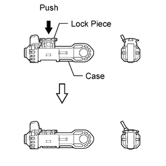
Push the lock piece into the case with slider held against the inhibitor wall.
-
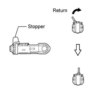
Return the stopper to prevent the lock from being released.
Note
-
Push in the lock piece completely.
-
Make sure the cable length adjustment structure is locked securely.
-
-
-
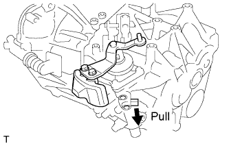
Release the pin that fixes the transmission outer lever.
-
Pull the pin toward the left front side of the vehicle.
-
-
-
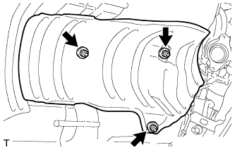
INSTALL FRONT NO. 1 FLOOR HEAT INSULATOR
-
Install the front No. 1 floor heat insulator with the 3 nuts.
- Torque:
- 5.5 N*m { 56 kgf*cm, 49 in.*lbf }
-
-
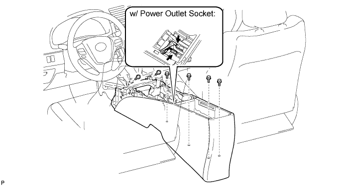
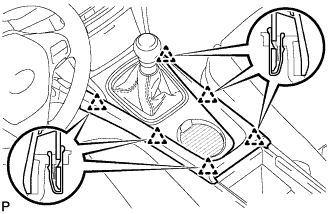
INSTALL CONSOLE BOX ASSEMBLY (w/o Console Box Lid)
-
Install the console box with the 2 screws.
-
w/ Power Outlet Socket:
-
Connect the connectors.
-
-
Install the 4 bolts.
-
-
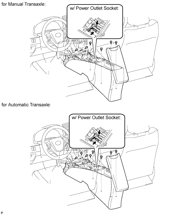
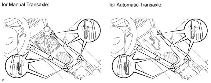
INSTALL CONSOLE BOX ASSEMBLY (w/ Console Box Lid)
-
for Manual Transaxle:
Install the console box with the 2 screws.
-
for Automatic Transaxle
Install the console box with the 4 screws.
-
w/ Power Outlet Socket:
-
Connect the connectors.
-
-
Install the 4 bolts.
-
-
INSTALL CONSOLE BOX CARPET (w/o Console Box Lid)
-
Install the 3 carpets.
-
-
INSTALL CONSOLE BOX CARPET (w/ Console Box Lid)
-
Install the 2 carpets.
-
-
INSTALL REAR CONSOLE BOX CUP HOLDER (w/ Console Box Lid)
-
Install the cup holder.
-
-
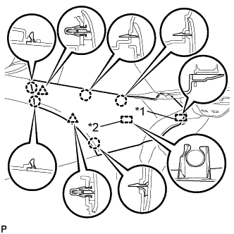
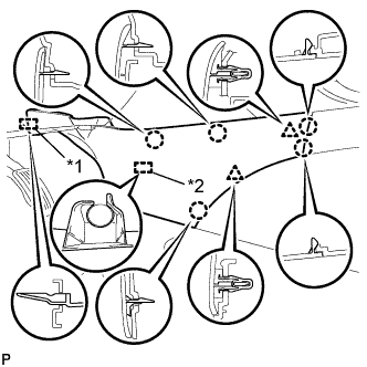
INSTALL REAR UPPER CONSOLE PANEL SUB-ASSEMBLY
-
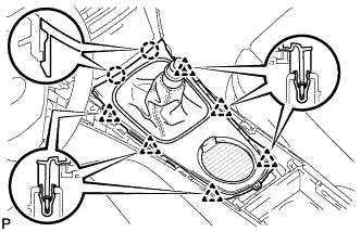
Attach the 2 claws and 6 clips to install the console panel.
-
Attach the cover to the shaft.
-
-
INSTALL SHIFT LEVER KNOB SUB-ASSEMBLY
-
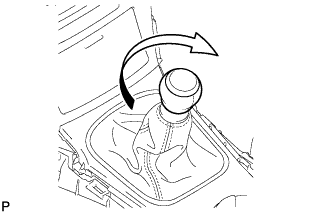
Install the shift lever knob and twist it in the direction indicated by the arrow.
-
-
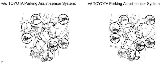
INSTALL INSTRUMENT PANEL FINISH PANEL END RH (for RHD)
-
w/o TOYOTA Parking Assist-sensor System:
-
Attach the 4 clips and 5 claws to install the panel end.
-
-
w/ TOYOTA Parking Assist-sensor System:
-
Connect the connector.
-
Attach the 4 clips and 5 claws to install the panel end.
-
-
-
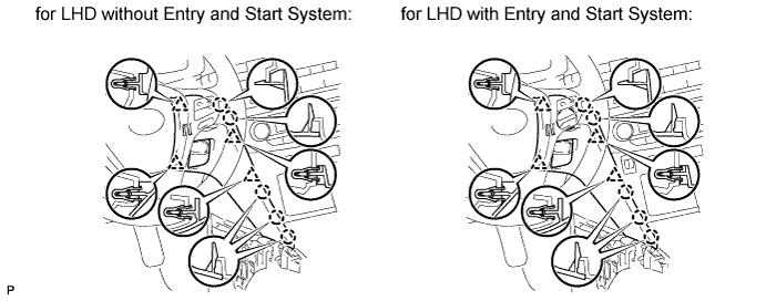
INSTALL INSTRUMENT PANEL FINISH PANEL END RH (for LHD)
-
Attach the 4 clips and 5 claws to install the panel end.
-
-
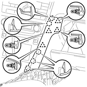
INSTALL INSTRUMENT PANEL FINISH PANEL END LH
-
Attach the 4 clips and 5 claws to install the panel end.
-
-
INSTALL NO. 3 BOX PANEL (w/ Console Box Lid)
-
When replacing the No. 3 box panel with a new one:
-
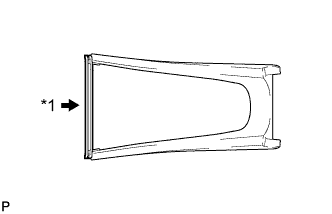
Text in Illustration *1 Cut Cut off the rib (the piece used to maintain the shape of the panel) shown in the illustration.
-
-
Attach the 6 clips to install the box panel.
-
-
INSTALL NO. 3 BOX PANEL (w/o Console Box Lid)
-
When replacing the No. 3 box panel with a new one:
-
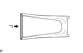
Text in Illustration *1 Cut Cut off the rib (the piece used to maintain the shape of the panel) shown in the illustration.
-
-
Attach the 6 clips to install the box panel.
-
-
INSTALL LOWER NO. 1 INSTRUMENT PANEL FINISH PANEL
-
Text in Illustration *1 Guide *2 Clamp Attach the guide near the front of the vehicle.
-
Attach the clamp.
-
Attach the 2 clips and 5 claws to install the finish panel.
-
-
INSTALL LOWER NO. 2 INSTRUMENT PANEL FINISH PANEL
-
Text in Illustration *1 Guide *2 Clamp Attach the guide near the front of the vehicle.
-
Attach the clamp.
-
Attach the 2 clips and 5 claws to install the finish panel.
-
-
INSTALL AIR CLEANER CASE
-
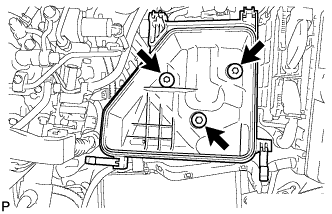
Install the air cleaner case with the 3 bolts.
- Torque:
- 7.0 N*m { 71 kgf*cm, 62 in.*lbf }
-
-
INSTALL AIR CLEANER FILTER ELEMENT SUB-ASSEMBLY
-
INSTALL AIR CLEANER CAP SUB-ASSEMBLY
-
Connect the air cleaner hose.
-
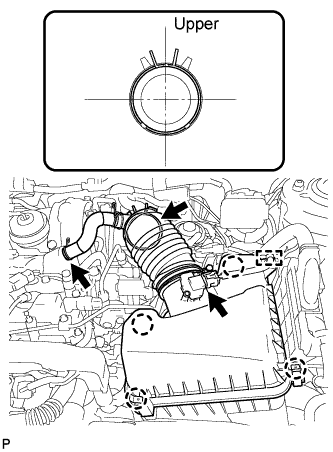
Attach the 4 clamps to install the air cleaner cap.
-
Connect the No. 2 ventilation hose.
-
Attach the clamp and connect the mass air flow meter connector.
-
-
INSTALL BATTERY CARRIER
-
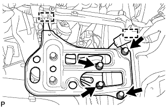
Install the battery carrier with the 4 bolts.
- Torque:
- 19 N*m { 189 kgf*cm, 14 ft.*lbf }
-
Attach the 2 clamps to connect the wire harness.
-
-
INSTALL BATTERY TRAY
-
INSTALL BATTERY
-
INSTALL BATTERY CLAMP SUB-ASSEMBLY
-
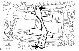
Attach the hook of the battery clamp to the battery carrier.
-
Partially tighten the nut and temporarily install the bolt.
-
Adjust the battery clamp position.
-
Tighten the nut and bolt.
- Torque:
- for bolt
- 17 N*m { 168 kgf*cm, 12 ft.*lbf }
- for nut
- 3.5 N*m { 36 kgf*cm, 31 in.*lbf }
-
-
INSTALL NO. 1 ENGINE COVER
-
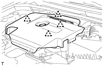
Attach the 4 clips to install the No. 1 engine cover.
-
-
INSTALL RADIATOR SUPPORT OPENING COVER
-
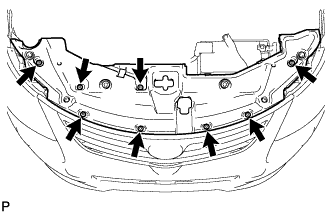
Install the radiator support opening cover with the 8 clips.
-
-
INSTALL FRONT EXHAUST PIPE ASSEMBLY
-
Install the front exhaust pipe assembly Click here.
-