ROOF HEADLINING (for Wagon) INSTALLATION

Tech Tips
A bolt without a torque specification is shown in the standard bolt chart Click here.
-
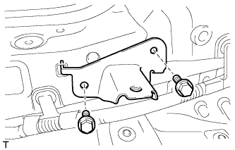
INSTALL TONNEAU COVER HOLDER BRACKET LH (w/ Partition Net)
-
Install the tonneau cover holder bracket with the 2 bolts.
-
-
INSTALL TONNEAU COVER HOLDER BRACKET RH (w/ Partition Net)
Tech Tips
Use the same procedure described for the LH side.
-
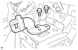
INSTALL NO. 2 DECK BOARD BRACKET
-
Install the No. 2 deck board bracket with the 2 bolts.
- Torque:
- 18 N*m { 184 kgf*cm, 13 ft.*lbf }
-
-
INSTALL NO. 1 DECK BOARD BRACKET
Tech Tips
Use the same procedure described for the No. 2 deck board bracket.
-
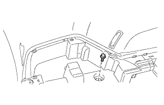
INSTALL NO. 4 LUGGAGE COMPARTMENT TRIM BRACKET (w/o Deck Rail)
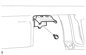
-
Install the No. 4 luggage compartment trim bracket with the bolt.
- Torque:
- 7.8 N*m { 80 kgf*cm, 69 in.*lbf }
-
-
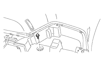
INSTALL NO. 3 LUGGAGE COMPARTMENT TRIM BRACKET (w/o Deck Rail)
Tech Tips
Use the same procedure described for the No. 4 luggage compartment trim bracket.
-
INSTALL FRONT DECK RAIL BRACKET LH (w/ Deck Rail)
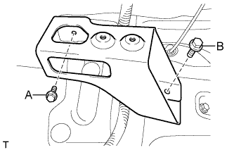
-
Install the front deck rail bracket with the 2 bolts.
- Torque:
- for bolt A
- 7.8 N*m { 80 kgf*cm, 69 in.*lbf }
- for bolt B
- 42 N*m { 428 kgf*cm, 31 ft.*lbf }
-
-
INSTALL FRONT DECK RAIL BRACKET RH (w/ Deck Rail)
Tech Tips
Use the same procedure described for the LH side.
-
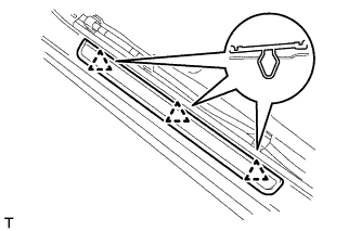
INSTALL REAR NO. 3 SIDE RAIL SPACER LH
-
Attach the 2 claws to install the No. 3 side rail spacer.
-
-
INSTALL REAR NO. 3 SIDE RAIL SPACER RH
Tech Tips
Use the same procedure described for the LH side.
-
INSTALL REAR NO. 2 SIDE RAIL SPACER LH
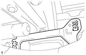
-
Attach the 2 claws to install the No. 2 side rail spacer.
-
-
INSTALL REAR NO. 2 SIDE RAIL SPACER RH
Tech Tips
Use the same procedure described for the LH side.
-
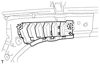
INSTALL FRONT SHOULDER BELT ANCHOR PLATE SUB-ASSEMBLY LH
-
Attach the 5 claws to install the front shoulder belt anchor plate.
-
-
INSTALL FRONT SHOULDER BELT ANCHOR PLATE SUB-ASSEMBLY RH
Tech Tips
Use the same procedure described for the LH side.
-
INSTALL REAR DOOR SCUFF PLATE OUTSIDE LH
-
Attach the 2 clips to install the rear door scuff plate outside.
-
-
INSTALL REAR DOOR SCUFF PLATE OUTSIDE RH
Tech Tips
Use the same procedure described for the LH side.
-
INSTALL FRONT DOOR SCUFF PLATE OUTSIDE LH
-
Attach the 3 clips to install the front door scuff plate outside.
-
-
INSTALL FRONT DOOR SCUFF PLATE OUTSIDE RH
Tech Tips
Use the same procedure described for the LH side.
-
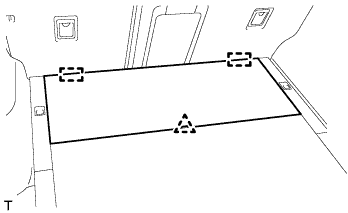
INSTALL ROOF HEADLINING ASSEMBLY
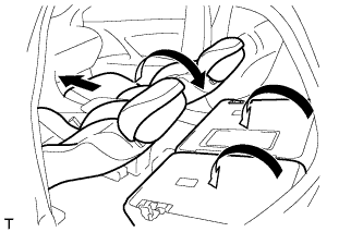
Tech Tips
Before installing the roof headlining, move the front seats and rear seat to the positions shown in the illustration.
-
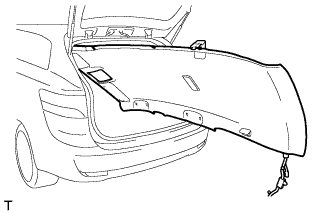
Place the roof headlining into the vehicle through the back door.
Note
Be careful not to damage the roof headlining when placing it in the cabin.
-
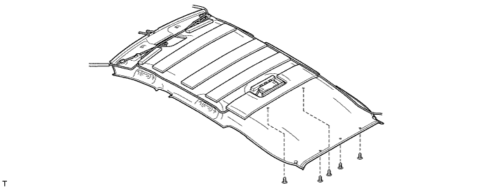
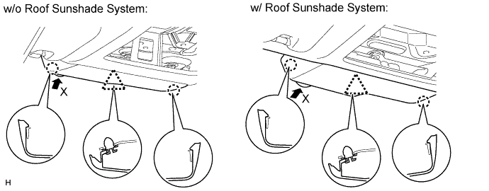
w/o Roof Sunshade System:
-
Install the roof headlining with the 5 clips.
-
-
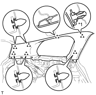
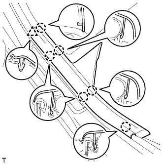
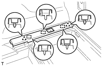
w/ Roof Sunshade System:
-
Attach the 3 guides and 12 fasteners to install the roof headlining.
-
Install the 5 clips.
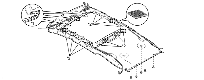
Text in Illustration *1 Guide *2 Fastener
-
-
for LHD:
-
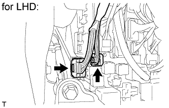
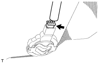
Connect the 2 roof wire connectors.
-
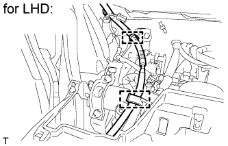
Connect the 2 clamps.
-
-
for RHD:
-
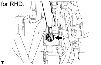
Connect the roof wire connector.
-
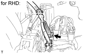
Connect the 2 clamps and connector.
-
-
Connect the 4 clamps to the front pillar LH.
-
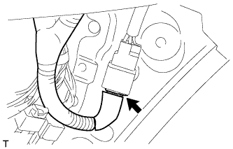
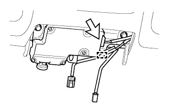
w/ Roof Sunshade System:
Connect the connector.
-
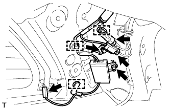
Install the antenna with the 2 bolts.
-
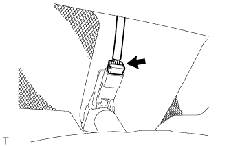
Connect the 3 clamps to the rear pillar RH.
-
Connect the 3 connectors.
-
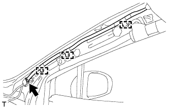
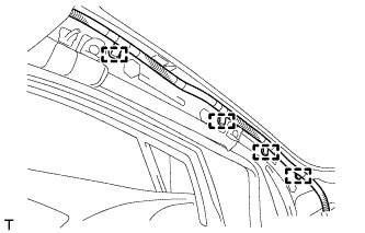
Connect the 3 clamps to the front pillar RH.
-
Connect the connector.
-
w/ Lane Keeping Assist System:
Tech Tips
-
Use the same procedure for RHD and LHD vehicles.
-
The procedure listed below is for LHD vehicles.
-
Connect the connector and attach the clamp.
-
-
w/ Rain Sensor:
Connect the rain sensor connector.
-
w/ EC Mirror:
Connect the EC mirror connector.
-
-
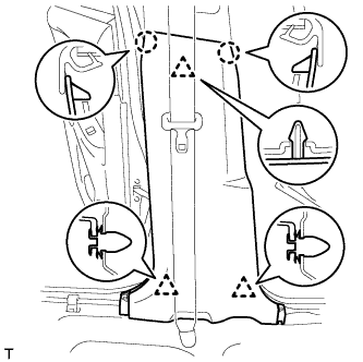
INSTALL REAR ROOM PARTITION NET HOOK LH
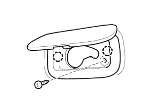
-
Attach the 2 claws to install the rear room partition net hook.
-
Install the screw.
-
-
INSTALL REAR ROOM PARTITION NET HOOK RH
Tech Tips
Use the same procedure described for the LH side.
-
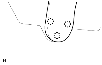
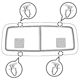
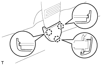
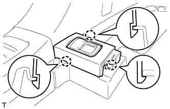
INSTALL ASSIST GRIP SUB-ASSEMBLY
Tech Tips
Use the same procedure for the other assist grip.
-
Assemble the assist grip as shown in the illustration.
-
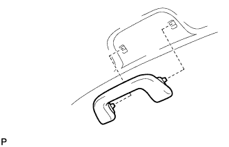
Install the assist grip.
-
-
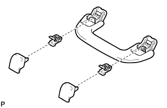
INSTALL REAR ASSIST GRIP ASSEMBLY LH
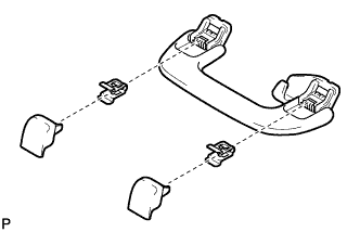
-
Assemble the rear assist grip as shown in the illustration.
-
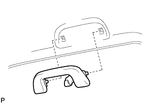
Install the rear assist grip.
-
-
INSTALL REAR ASSIST GRIP ASSEMBLY RH
Tech Tips
Use the same procedure described for the LH side.
-
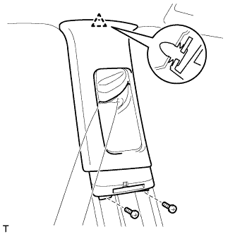
INSTALL VISOR HOLDER
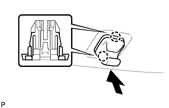
Tech Tips
Use the same procedure to install the visor holder on the other side.
-
Attach the 2 claws.
-
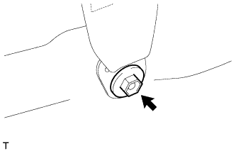
Push in the visor holder as shown in the illustration.
-
-
INSTALL VISOR ASSEMBLY LH
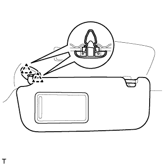
-
Attach the 2 clips to install the visor.
-
-
INSTALL VISOR ASSEMBLY RH
Tech Tips
Use the same procedure described for the LH side.
-
INSTALL RAIN SENSOR COVER (w/ Rain Sensor)
-
Attach the 3 claws to install the No. 1 rain sensor cover.
-
-
INSTALL INNER REAR VIEW MIRROR STAY HOLDER COVER (w/ EC Mirror)
-
w/o Rear Monitor:
Install the inner rear view mirror stay holder cover Click here.
-
w/ Rear Monitor:
Install the inner rear view mirror stay holder cover Click here.
-
-
INSTALL NO. 1 ROOM LIGHT ASSEMBLY
-
Connect the connector.
-
Attach the 4 clips to install the No. 1 room light.
-
-
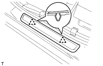
INSTALL FRONT ROOF TOP GARNISH (w/ Lane Keeping Assist System)
-
Attach the 2 claws and clip to install the front roof top garnish.
Note
When removing the rain sensor cover, do not apply force to the lane recognition camera sensor assembly areas labeled "X".
-
-
INSTALL MAP LIGHT ASSEMBLY
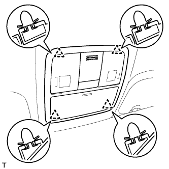
-
Connect the connector.
-
Attach the 4 clips to install the map light.
-
-
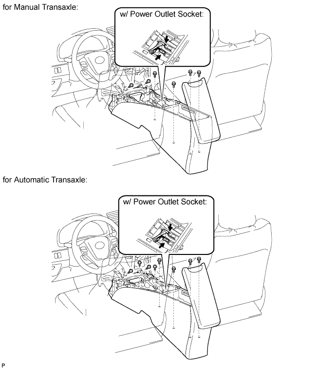
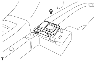
INSTALL COIN BOX ASSEMBLY
-
for Manual Transaxle:
Install the console box with the 2 screws.
-
for Automatic Transaxle
Install the console box with the 4 screws.
-
w/ Power Outlet Socket:
-
Connect the connectors.
-
-
Install the 4 bolts.
-
-
INSTALL UPPER INSTRUMENT PANEL SUB-ASSEMBLY
Tech Tips
-
Use the same procedure for RHD and LHD vehicles.
-
The procedure listed below is for LHD vehicles.
-
Install the upper instrument panel sub-assembly Click here.
-
-
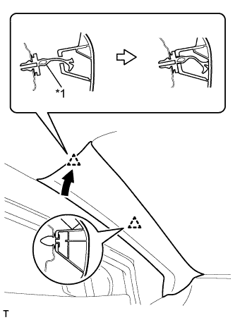
INSTALL INNER ROOF SIDE GARNISH LH
Text in Illustration *1 Clip A
-
Install a new clip A to the inner roof side garnish.
-
Attach the 7 clips to install the inner roof side garnish.
-
-
INSTALL INNER ROOF SIDE GARNISH RH
Tech Tips
Use the same procedure described for the LH side.
-
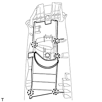
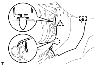
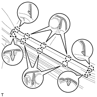
INSTALL DECK TRIM SIDE PANEL ASSEMBLY LH
-
Pass the fuel lid opener cable through the deck trim side panel.
-
Connect the connector.
-
Attach the 7 clips and 3 claws to install the deck trim side panel.
-
Install the bolt and clip.
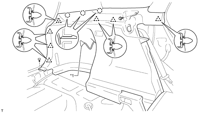
Text in Illustration *1 Fuel Lid Opener Cable - -
-
-
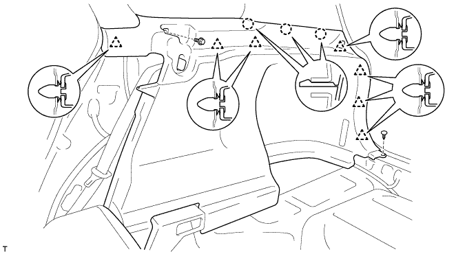
INSTALL DECK TRIM SIDE PANEL ASSEMBLY RH
-
Attach the 7 clips and 3 claws to install the deck trim side panel.
-
Install the bolt and clip.
-
-
INSTALL INNER ROOF SIDE GARNISH CAP LH
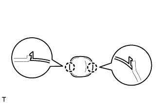
-
Attach the 2 claws to install the inner roof side garnish cap.
-
-
INSTALL INNER ROOF SIDE GARNISH CAP RH
Tech Tips
Use the same procedure described for the LH side.
-
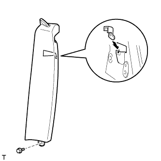
INSTALL CENTER PILLAR GARNISH LH
-
Pass the front seat outer belt floor anchor through the center pillar garnish.
-
Attach the clip to install the center pillar garnish.
-
Install the 2 screws.
-
Install the front seat outer belt floor anchor with the bolt.
- Torque:
- 41 N*m { 418 kgf*cm, 30 ft.*lbf }
-
-
INSTALL CENTER PILLAR GARNISH RH
Tech Tips
Use the same procedure described for the LH side.
-
INSTALL LAP BELT OUTER ANCHOR COVER
Tech Tips
Use the same procedure for the other lap belt outer anchor cover.
-
Attach the 3 claws to install the lap belt outer anchor cover.
-
-
INSTALL LOWER CENTER PILLAR GARNISH LH
-
Attach the 2 claws and 3 clips to install the lower center pillar garnish.
-
-
INSTALL LOWER CENTER PILLAR GARNISH RH
Tech Tips
Use the same procedure described for the LH side.
-
INSTALL FRONT PILLAR GARNISH LH
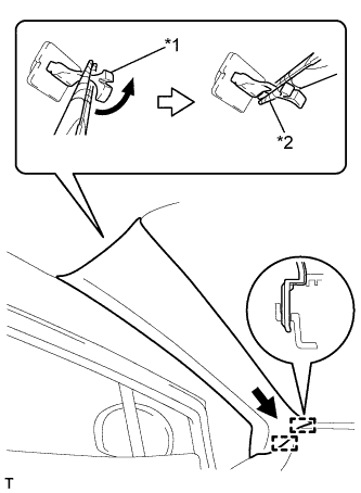
Text in Illustration *1 Front Pillar Garnish Clip *2 Protective Tape
-
Remove the protective cover.
-
Attach the 2 guides.
-
Turn the end of the front pillar garnish clip 90° with needle-nose pliers and install it to the front pillar garnish.
Tech Tips
Tape the tips of the needle-nose pliers before use.
-
Text in Illustration *1 Front Pillar Garnish Clip Attach the 2 clips to install the front pillar garnish.
-
-
INSTALL FRONT PILLAR GARNISH RH
Tech Tips
Use the same procedure described for the LH side.
-
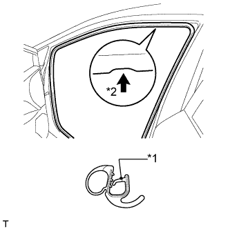
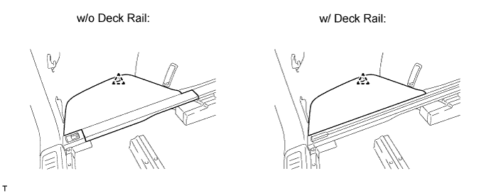
INSTALL BACK DOOR WEATHERSTRIP
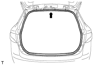
-
Align the center mark of the back door weatherstrip with the position indicated by the arrow in the illustration and install the back door weatherstrip.
-
-
INSTALL REAR DOOR OPENING TRIM WEATHERSTRIP LH
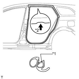
Text in Illustration *1 Paint Mark *2 Mark Position
-
Install the rear door opening trim weatherstrip as shown in the illustration.
-
-
INSTALL REAR DOOR OPENING TRIM WEATHERSTRIP RH
Tech Tips
Use the same procedure described for the LH side.
-
INSTALL REAR DOOR SCUFF PLATE LH
-
Attach the clip and 6 claws to install the front door scuff plate.
-
-
INSTALL REAR DOOR SCUFF PLATE RH
Tech Tips
Use the same procedure described for the LH side.
-
INSTALL FRONT DOOR OPENING TRIM WEATHERSTRIP LH
Text in Illustration *1 Paint Mark *2 Mark Position
-
Install the front door opening trim weatherstrip as shown in the illustration.
-
-
INSTALL FRONT DOOR OPENING TRIM WEATHERSTRIP RH
Tech Tips
Use the same procedure described for the LH side.
-
INSTALL COWL SIDE TRIM BOARD LH
-
Attach the clip, claw and guide to install the cowl side trim board.
-
-
INSTALL COWL SIDE TRIM BOARD RH
Tech Tips
Use the same procedure described for the LH side.
-
INSTALL FRONT DOOR SCUFF PLATE LH
-
Attach the 2 clips and 8 claws to install the front door scuff plate.
-
-
INSTALL FRONT DOOR SCUFF PLATE RH
Tech Tips
Use the same procedure described for the LH side.
-
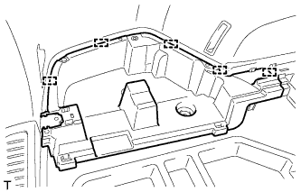
INSTALL FRONT DECK FLOOR BOX
-
Attach the 4 guides to install the front deck floor box.
-
Install the 2 clips.
-
-
INSTALL REAR FLOOR FINISH PLATE
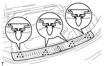
-
Attach the 4 clips to install the rear floor finish plate.
-
-
INSTALL DECK FLOOR BOX LH
-
Attach the 5 guides to install the deck floor box.
-
-
INSTALL DECK FLOOR BOX RH
Tech Tips
Use the same procedure described for the LH side.
-
INSTALL ROPE HOOK ASSEMBLY (w/o Deck Rail)
Tech Tips
Use the same procedure for all the rope hooks.
-
Install the rope hook with the bolt.
- Torque:
- 18 N*m { 184 kgf*cm, 13 ft.*lbf }
-
-
INSTALL NO. 6 DECK SIDE TRIM COVER (w/o Deck Rail)
-
Attach the 3 claws to install the No. 6 deck side trim cover.
-
-
INSTALL NO. 5 DECK SIDE TRIM COVER (w/o Deck Rail)
Tech Tips
Use the same procedure described for the No. 6 deck side trim cover.
-
INSTALL NO. 2 DECK SIDE TRIM COVER (w/o Deck Rail)
-
Attach the 2 clips and 3 guides to install the No. 2 deck side trim cover.
-
-
INSTALL NO. 1 DECK SIDE TRIM COVER (w/o Deck Rail)
Tech Tips
Use the same procedure described for the No. 2 deck side trim cover.
-
INSTALL FLOOR SIDE RAIL LH (w/ Deck Rail)
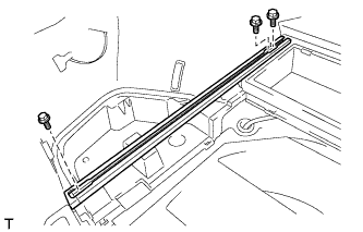
-
Install the floor side rail with the 3 bolts.
- Torque:
- 18 N*m { 184 kgf*cm, 13 ft.*lbf }
-
-
INSTALL FLOOR SIDE RAIL RH (w/ Deck Rail)
Tech Tips
Use the same procedure described for the LH side.
-
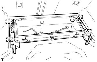
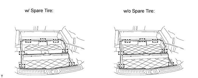
INSTALL REAR DECK FLOOR BOX
-
Attach the 7 guides to install the rear deck floor box.
-
Install the bolt.
-
Install the bolt.
-
-
INSTALL NO. 3 DECK BOARD SUB-ASSEMBLY
-
Attach the clip to install the No. 3 deck board.
-
-
INSTALL NO. 2 DECK BOARD SUB-ASSEMBLY
Tech Tips
Use the same procedure described for the No. 3 deck board.
-
INSTALL DECK BOARD SUB-ASSEMBLY
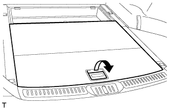
-
Pull the lever to install the deck board.
-
-
INSTALL DECK BOARD ASSEMBLY
-
Attach the clip and 2 guides to install the deck board.
-
-
INSTALL LOWER DECK TRIM SIDE BOARD LH (w/ Partition Board)
-
Install the lower deck trim side board.
-
-
INSTALL LOWER DECK TRIM SIDE BOARD RH (w/ Partition Board)
-
Install the lower deck trim side board.
-
-
INSTALL ROOM PARTITION NET ASSEMBLY (w/ Partition Net)
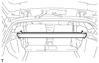
-
Install the room partition net.
-
-
INSTALL TONNEAU COVER ASSEMBLY (w/ Tonneau Cover)
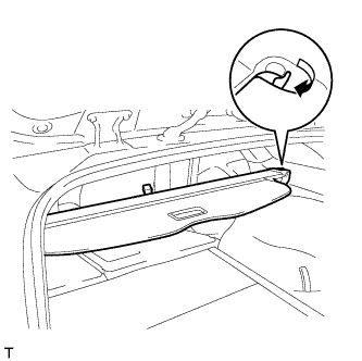
-
Pull the lever to install the tonneau cover.
-
-
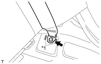
INSTALL REAR SIDE SEATBACK ASSEMBLY LH
-
Install the claw as shown in the illustration.
-
Install the side seatback with the bolt.
- Torque:
- 7.8 N*m { 80 kgf*cm, 69 in.*lbf }
-
Text in Illustration *1 Protruding Part Install the rear seat 3 point type belt anchor with the bolt.
- Torque:
- 41 N*m { 418 kgf*cm, 30 ft.*lbf }
Note
Do not allow the anchor part of the rear seat 3 point type belt to overlap the protruding parts of the floor panel.
-
Install the seat belt to the belt guide.
-
Attach the claw to close the cap of the rear seat shoulder belt guide.
-
Check if the ELR locks.
Note
The check should be performed with the outer belt assembly installed.
-
With the belt assembly installed, check that the belt locks when it is pulled out quickly.
-
-
-
INSTALL REAR SIDE SEATBACK ASSEMBLY RH
Tech Tips
Use the same procedure described for the LH side.
-
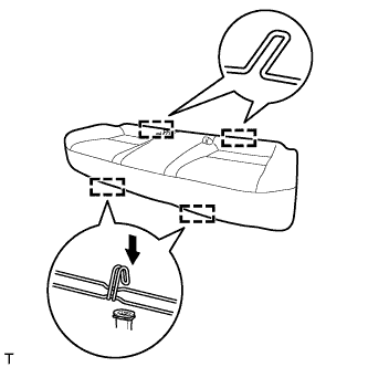
INSTALL BENCH TYPE REAR SEAT CUSHION ASSEMBLY
-
Attach the 2 rear hooks of the seat cushion to the seatback.
-
Attach the 2 front hooks to install the seat cushion.
-
Confirm that the seat cushion is firmly installed.
Note
When installing the seat cushion, make sure the seat belt buckle is not under the seat cushion.
-
-
CONNECT CABLE TO NEGATIVE BATTERY TERMINAL
Note
When disconnecting the cable, some systems need to be initialized after the cable is reconnected Click here.