ROOF SUNSHADE SYSTEM, Diagnostic DTC:B2342

| DTC Code | DTC Name |
|---|---|
| B2342 | Switch Failure |
DESCRIPTION
This DTC is stored when the sliding roof drive gear sub-assembly detects that the roof sunshade switch in the map light assembly is stuck for 30 seconds or more.
| DTC Code | DTC Detection Condition | Trouble Area |
|---|---|---|
| B2342 | Sliding roof drive gear sub-assembly detects that the roof sunshade switch in the map light assembly is stuck for 30 seconds or more. |
|
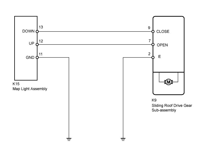
WIRING DIAGRAM
INSPECTION PROCEDURE
PROCEDURE
-
CHECK FOR DTC
-
Clear the DTCs Click here.
-
Check the DTCs Click here.
Result Result Proceed to DTC B2342 is output A No DTC is output B
B 
USE SIMULATION METHOD TO CHECK Click here
A 
-
-
READ VALUE USING INTELLIGENT TESTER (SWITCH STATUS)
-
Use the Data List to check if the roof sunshade switch is functioning properly Click here.
Sliding Roof Tester Display Measurement Item/Range Normal Condition Diagnostic Note Close Switch Failure(Current) Close switch failure signal (Current)/Fail or Not Fail Fail: Roof sunshade close signal failure (Current)
Not Fail: No roof sunshade close signal failure (Current)
- Open Switch Failure(Current) Open switch failure signal (Current)/Fail or Not Fail Fail: Roof sunshade open signal failure (Current)
Not Fail: No roof sunshade open signal failure (Current)
- Close Switch Failure(Past) Close switch failure signal (Past)/Fail or Not Fail Fail: Roof sunshade close signal failure (Past)
Not Fail: No roof sunshade close signal failure (Past)
- Open Switch Failure(Past) Open switch failure signal (Past)/Fail or Not Fail Fail: Roof sunshade open signal failure (Past)
Not Fail: No roof sunshade open signal failure (Past)
- OK "Not Fail" appears on screen.
NG 
INSPECT MAP LIGHT ASSEMBLY (ROOF SUNSHADE SWITCH) Click here
OK 
REPLACE SLIDING ROOF DRIVE GEAR SUB-ASSEMBLY Click here
-
-
INSPECT MAP LIGHT ASSEMBLY (ROOF SUNSHADE SWITCH)
-
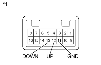
Text in Illustration *1 Component without harness connected
(Map Light Assembly)
Remove the map light assembly.
-
for Sedan : Click here
-
for Wagon : Click here
-
-
Measure the resistance according to the value(s) in the table below.
Standard Resistance Tester Connection Switch Condition Specified Condition 12 (UP) - 11 (GND) Open switch is pressed Below 1 Ω 12 (UP) - 11 (GND) Open switch is not pressed 10 kΩ or higher 13 (DOWN) - 11 (GND) Close switch is pressed Below 1 Ω 13 (DOWN) - 11 (GND) Close switch is not pressed 10 kΩ or higher Result Result Proceed to OK A NG (for Sedan) B NG (for Wagon) C
B
REPLACE MAP LIGHT ASSEMBLY Click here
C
REPLACE MAP LIGHT ASSEMBLY Click here
A
-
-
CHECK HARNESS AND CONNECTOR (SLIDING ROOF DRIVE GEAR SUB-ASSEMBLY - MAP LIGHT ASSEMBLY)
-
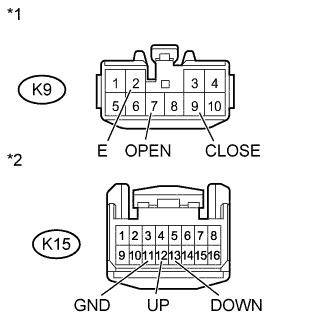
Text in Illustration *1 Front view of wire harness connector
(to Sliding Roof Drive Gear Sub-assembly)
*2 Front view of wire harness connector
(to Map Light Assembly)
Disconnect the K9 sliding roof drive gear sub-assembly connector.
-
Disconnect the K15 map light assembly connector.
-
Measure the resistance according to the value(s) in the table below.
Standard Resistance Tester Connection Condition Specified Condition K9-7 (OPEN) - K15-12 (UP) Always Below 1 Ω K9-9 (CLOSE) - K15-13 (DOWN) Always Below 1 Ω K15-11 (GND) - Body ground Always Below 1 Ω K9-2 (E) - Body ground Always Below 1 Ω K9-7 (OPEN) or K15-12 (UP) - Body ground Always 10 kΩ or higher K9-9 (CLOSE) or K15-13 (DOWN) - Body ground Always 10 kΩ or higher
NG
REPAIR OR REPLACE HARNESS OR CONNECTOR
OK
REPLACE SLIDING ROOF DRIVE GEAR SUB-ASSEMBLY Click here
-