ROOF SUNSHADE SYSTEM Power Source Circuit
DESCRIPTION
If the sliding function does not operate, there may be a malfunction in the sliding roof drive gear power source circuit.
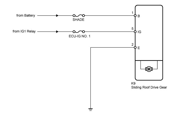
WIRING DIAGRAM
INSPECTION PROCEDURE
Note
Inspect the fuses for circuits related to this system before performing the following inspection procedure.
PROCEDURE
-
CHECK HARNESS AND CONNECTOR (SLIDING ROOF DRIVE GEAR SUB-ASSEMBLY - BATTERY AND BODY GROUND)
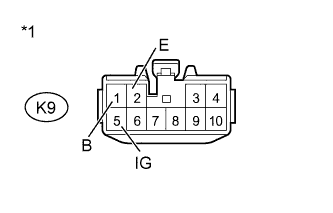
Text in Illustration *1 Front view of wire harness connector
(to Sliding Roof Drive Gear)
-
Disconnect the K9 drive gear connector.
-
Measure the resistance and voltage according to the value(s) in the table below.
Standard Resistance Tester Connection Condition Specified Condition K9-2 (E) - Body ground Always Below 1 Ω Standard Voltage Tester Connection Switch Condition Specified Condition K9-1 (B) - Body ground Always 11 to 14 V K9-5 (IG) - Body ground Ignition switch off Below 1 V K9-5 (IG) - Body ground Ignition switch ON 11 to 14 V
NG 
REPAIR OR REPLACE HARNESS OR CONNECTOR
OK 
REPLACE SLIDING ROOF DRIVE GEAR SUB-ASSEMBLY Click here
-