AIR CONDITIONING UNIT (for Manual Air Conditioning System) REMOVAL

Tech Tips
-
Use the same procedure for LHD and RHD vehicles.
-
The procedure listed below is for LHD vehicles.
-
REMOVE NO. 1 ENGINE COVER
-
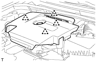
Hold the rear of the cover and slowly raise it to detach the clip on the rear of the cover. Continue to raise the cover to detach the 3 clips on the front and side of the cover and remove the cover.
Note
Attempting to disengage both front and rear clips at the same time may cause the cover to break.
-
-
REMOVE RADIATOR SUPPORT OPENING COVER
-
Remove the 7 clips and radiator support opening cover.
-
-
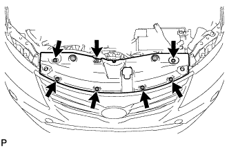
REMOVE FRONT LOWER BUMPER ABSORBER
-
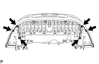
Remove the 4 screws and 2 bolts.
-
Remove the 8 bolts and 3 screws.
-
Detach the 2 hooks of the front lower bumper absorber from the installation holes on the body and remove the front lower bumper absorber.
-
-
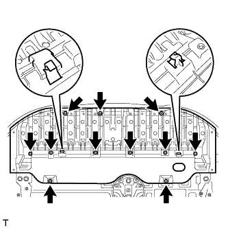
REMOVE NO. 1 ENGINE UNDER COVER
-
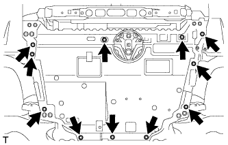
Remove the 11 clips and engine under cover.
-
-
RECOVER REFRIGERANT FROM REFRIGERATION SYSTEM
-
Start the engine.
-
Turn the A/C switch on.
-
Operate the cooler compressor while the engine speed is approximately 1000 rpm for 5 to 6 minutes to circulate the refrigerant and collect the compressor oil remaining in each component into the cooler compressor.
-
Stop the engine.
-
Recover the refrigerant from the A/C system using a refrigerant recovery unit.
-
-
DRAIN ENGINE COOLANT
-
for 1AD-FTV:
Drain the engine coolant Click here.
-
for 2AD-FHV:
Drain the engine coolant Click here.
-
for 2AD-FTV:
Drain the engine coolant Click here.
-
-
PRECAUTION
Note
After turning the ignition switch off, waiting time may be required before disconnecting the cable from the battery terminal. Therefore, make sure to read the disconnecting the cable from the battery terminal notice before proceeding with work Click here.
-
DISCONNECT CABLE FROM NEGATIVE BATTERY TERMINAL
CAUTION:
Wait at least 90 seconds after disconnecting the cable from the negative (-) battery terminal to disable the SRS system.
Note
When disconnecting the cable, some systems need to be initialized after the cable is reconnected Click here.
-
REMOVE FRONT WIPER MOTOR AND BRACKET
-
Remove the front wiper motor and bracket Click here.
-
-
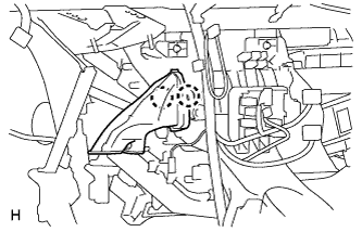
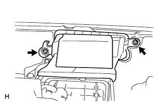
REMOVE DIFFERENTIAL PRESSURE SENSOR ASSEMBLY (for DPF)
-
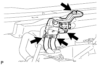
Detach the wire harness clamp and disconnect the sensor connector.
-
Remove the bolt and sensor.
-
Disconnect the 2 vacuum hoses.
-
-
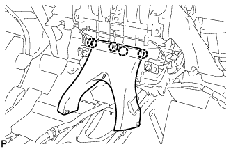
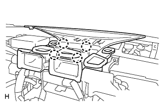
REMOVE OUTER COWL TOP PANEL SUB-ASSEMBLY
-
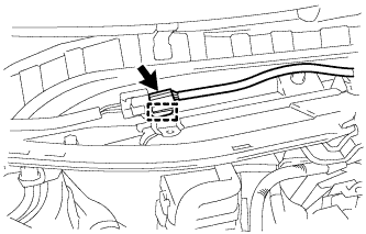
Disconnect the connector and detach the harness clamp.
-
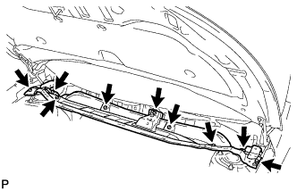
Remove the 9 bolts and outer cowl top panel.
-
-
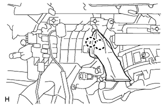
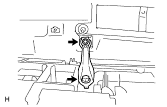
DISCONNECT AIR CONDITIONING TUBE ASSEMBLY
-
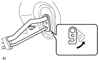
Remove the bolt.
-
Detach the plate as shown in the illustration.
-
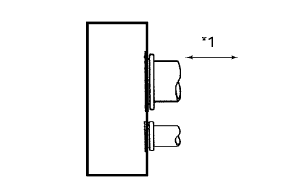
Text in Illustration *1 Disconnect Tube by Hand Disconnect the air conditioning tube assembly.
Note
-
Do not use a screwdriver or similar tool to disconnect the tube.
-
Seal the openings of the disconnected parts using vinyl tape to prevent moisture and foreign matter from entering them.
-
-
Remove the 2 O-rings from the air conditioning tube assembly.
-
-
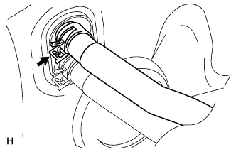
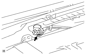
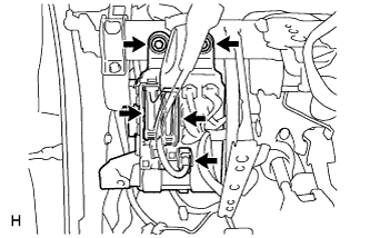
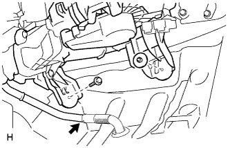
DISCONNECT HEATER WATER OUTLET HOSE
-
Using pliers, grip the claws of the clip and slide the clip.
-
Disconnect the heater water outlet hose.
-
-
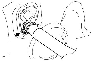
DISCONNECT HEATER WATER INLET HOSE
-
Using pliers, grip the claws of the clip and slide the clip.
-
Disconnect the heater water inlet hose.
-
-
REMOVE UPPER INSTRUMENT PANEL SUB-ASSEMBLY
-
Remove the upper instrument panel Click here.
-
-
REMOVE LOWER INSTRUMENT PANEL SUB-ASSEMBLY
-
Remove the lower instrument panel Click here.
-
-
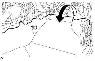
REMOVE REAR NO. 3 AIR DUCT
-
Remove the clip.
-
Fold back the floor carpet.
-
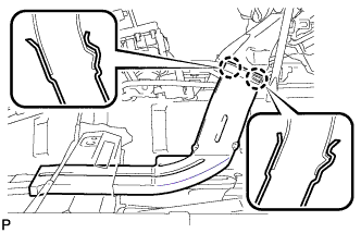
Detach the 2 claws and remove the rear No. 3 air duct.
-
-
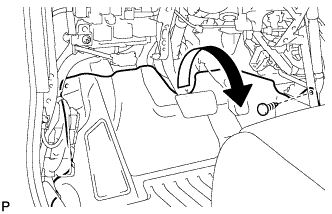
REMOVE REAR NO. 2 AIR DUCT
-
Remove the clip.
-
Fold back the floor carpet.
-
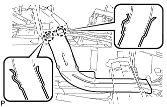
Detach the 2 claws and remove the rear No. 2 air duct.
-
-
REMOVE REAR NO. 1 AIR DUCT
-
Detach the 4 claws and remove the rear No. 1 air duct.
-
-
REMOVE NO. 2 AIR DUCT SUB-ASSEMBLY
-
Detach the 2 claws and remove the duct.
-
-
REMOVE NO. 1 AIR DUCT SUB-ASSEMBLY
-
Detach the 2 claws and remove the duct.
-
-
REMOVE STEERING COLUMN ASSEMBLY
-
for Manual Tilt and Manual Telescopic Steering Column:
Remove the steering column Click here.
-
for Power Tilt and Power Telescopic Steering Column:
Remove the steering column Click here.
-
-
REMOVE COOLER (SOLAR SENSOR) THERMISTOR
-
Disconnect the connector.
-
Detach the 2 claws and remove the sensor.
-
-
REMOVE DEFROSTER NOZZLE ASSEMBLY
-
Detach the 4 claws and remove the defroster nozzle assembly.
-
-
REMOVE AIR DUCT ASSEMBLY
-
Remove the 2 nuts and duct.
-
-
REMOVE CENTER INSTRUMENT PANEL TO COWL BRACE
-
Remove the 2 bolts and brace.
-
-
REMOVE POWER STEERING ECU ASSEMBLY
-
for LHD:
Remove the power steering ECU assembly Click here.
-
for RHD:
Remove the power steering ECU assembly Click here.
-
-
REMOVE MAIN BODY ECU (INSTRUMENT PANEL JUNCTION BLOCK ASSEMBLY)
-
Disconnect the 3 connectors.
-
Remove the 2 bolts and main body ECU.
-
-
REMOVE NO. 1 INSTRUMENT PANEL BRACE SUB-ASSEMBLY
-
Detach the 4 clamps.
-
Remove the nut, 2 bolts and brace.
-
-
REMOVE NO. 2 INSTRUMENT PANEL BRACE SUB-ASSEMBLY
-
Detach the clamp.
-
Remove the nut, 2 bolts and brace.
-
-
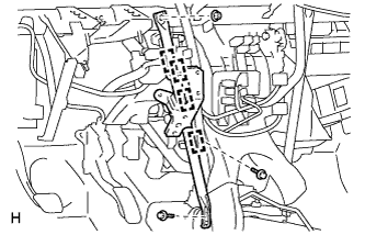
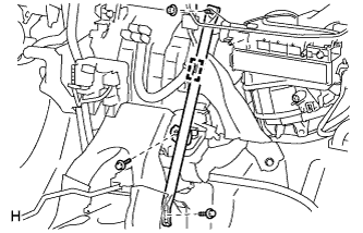
REMOVE INSTRUMENT PANEL REINFORCEMENT ASSEMBLY
-
Disconnect the clamps, connectors and wire harness.
-
Remove the instrument panel reinforcement.
-
for Manual Transaxle:
Remove the bolt from the clutch pedal.
-
Remove the bolts, screws and instrument panel reinforcement.
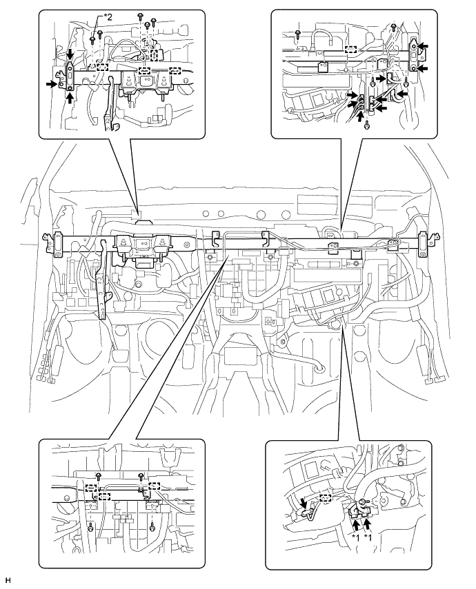
Text in Illustration *1 w/ PTC Heater *2 for Manual Transaxle
-
-
-
REMOVE AIR CONDITIONING UNIT
-
Disconnect the drain cooler hose.
-
Remove the nut, bolt and air conditioning unit.
-