AIR CONDITIONING UNIT (for Automatic Air Conditioning System) REASSEMBLY

Tech Tips
-
Use the same procedure for LHD and RHD vehicles.
-
The procedure listed below is for LHD vehicles.
-
A bolt without a torque specification is shown in the standard bolt chart Click here.
-
INSTALL FRONT EVAPORATOR TEMPERATURE SENSOR
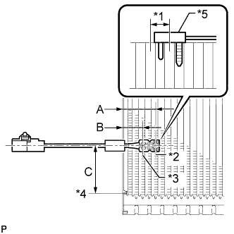
Text in Illustration *1 1 Fin *2 Sensor Part *3 Part Used to Hold Sensor in Place *4 from Tank *5 Front Evaporator Temperature Sensor Note
If reusing the evaporator, do not insert the sensor into a location where the sensor was previously inserted.
-
Insert the sensor to a location that is 1 fin to the right or left of its previous location.
Standard Area Specified Condition A 50 mm (1.97 in.) B 34.3 mm (1.35 in.) C 20.9 mm (1.97 in.)
-
-
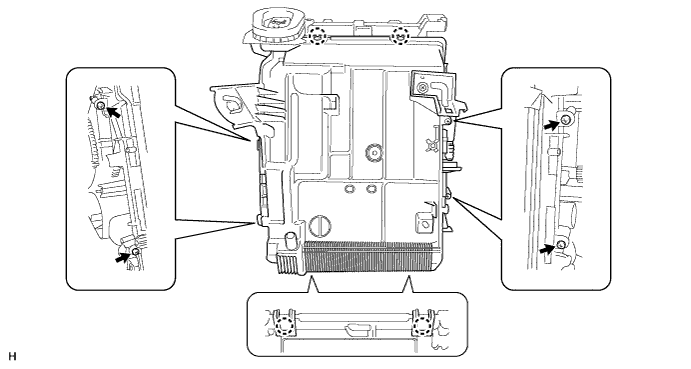
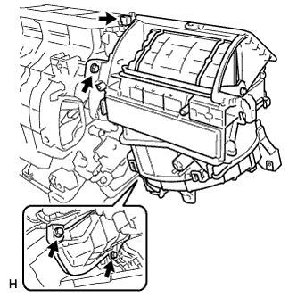
INSTALL NO. 1 COOLER EVAPORATOR SUB-ASSEMBLY
-
Install the evaporator.
-
Attach the clamp.
-
Attach the 4 claws to install the unit case.
-
Install the 4 screws.
-
-
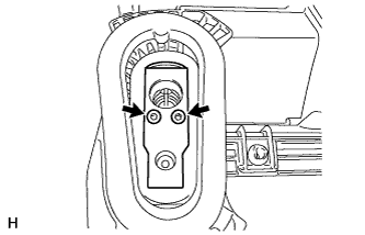
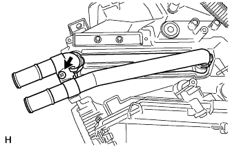
INSTALL COOLER EXPANSION VALVE
-
Sufficiently apply compressor oil to 2 new O-rings and the fitting surface of the hose joint.
Compressor oil ND-OIL 8 or equivalent -
Install the 2 O-rings to the No. 1 cooler evaporator sub-assembly.
-
Install the cooler expansion valve to the No. 1 cooler evaporator sub-assembly.
-
Using a 4 mm hexagon wrench, install the 2 bolts.
- Torque:
- 3.5 N*m { 36 kgf*cm, 31 in.*lbf }
-
-
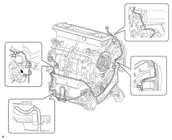
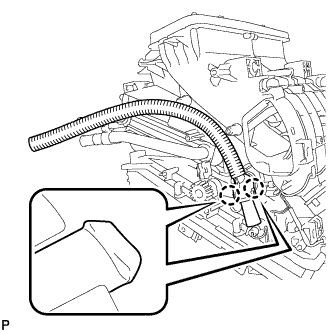
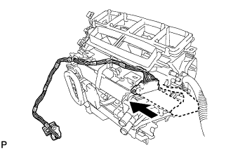
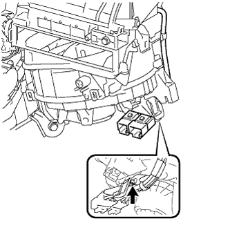
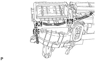
INSTALL AIR CONDITIONING HARNESS ASSEMBLY
-
Attach the clamps to install the harness.
-
Connect the connector.
-
-
INSTALL DRAIN COOLER HOSE
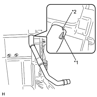
Text in Illustration *1 Alignment Mark *2 Protrusion
-
Install the drain cooler hose as shown in the illustration.
-
-
INSTALL ASPIRATOR
-
Attach the 2 claws to install the aspirator.
-
-
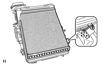
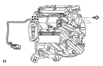
INSTALL AIR CONDITIONING RADIATOR ASSEMBLY
-
Install the radiator.
-
Install the bracket with the screw.
-
-
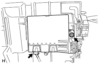
INSTALL PTC HEATER ASSEMBLY (w/ PTC Heater)
-
Install the PTC heater as shown in the illustration.
-
Install the 2 screws.
-
Attach the clamp.
-
-
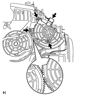
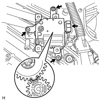
INSTALL MODE DAMPER SERVO SUB-ASSEMBLY
-
Set the damper servo so that the tooth of the gear engages with the cutout part as shown in the illustration to install the damper servo.
-
Install the 3 screws.
-
Connect the connector.
-
-
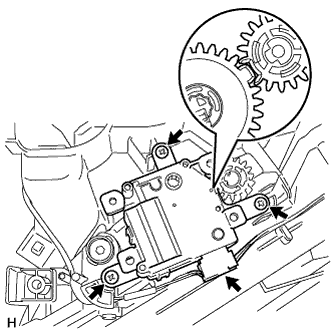
INSTALL AIR MIX DAMPER SERVO SUB-ASSEMBLY
-
Set the damper servo so that the tooth of the gear engages with the cutout part as shown in the illustration to install the damper servo.
-
Install the 3 screws.
-
Connect the connector.
-
-
INSTALL NO. 2 AIR MIX DAMPER SERVO SUB-ASSEMBLY
-
Set the damper servo so that the tooth of the gear engages with the cutout part as shown in the illustration to install the damper servo.
-
Install the 3 screws.
-
Connect the connector.
-
-
INSTALL AIR CONDITIONING AMPLIFIER ASSEMBLY
-
Install the amplifier assembly with the screw.
-
Connect the connector.
-
-
INSTALL BLOWER ASSEMBLY
-
Install the blower assembly with the 3 screws.
-
Connect the connector.
-
w/ PTC Heater:
Install the screw.
-
w/ PTC Heater:
Attach the 3 clamps.
-