CONDENSER INSTALLATION

-
INSTALL CONDENSER ASSEMBLY WITH RECEIVER
-
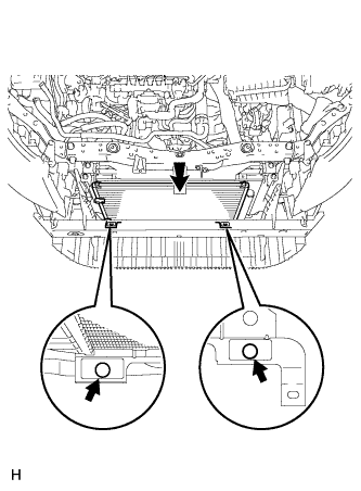
Install the condenser assembly with receiver as shown in the illustration.
Tech Tips
If the condenser is replaced with a new one, add compressor oil to a new condenser.
Capacity 40 cc (1.4 fl.oz) Compressor oil ND-OIL 8 or equivalent
-
-
INSTALL UPPER RADIATOR SUPPORT SUB-ASSEMBLY
-
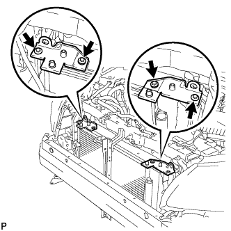
Install the upper radiator support sub-assembly LH and upper radiator support sub-assembly RH with the 4 bolts.
- Torque:
- 7.0 N*m { 71 kgf*cm, 62 in.*lbf }
-
-
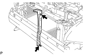
INSTALL UPPER RADIATOR SUPPORT
-
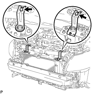
Install the 2 upper radiator supports with the 2 bolts.
- Torque:
- 19 N*m { 194 kgf*cm, 14 ft.*lbf }
-
-
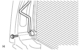
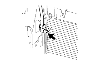
CONNECT SUCTION PIPE SUB-ASSEMBLY
-
Remove the attached vinyl tape from the pipe and the connecting part of the cooler condenser assembly.
-
Sufficiently apply compressor oil to a new O-ring and the fitting surface of the pipe joint.
Compressor oil ND-OIL 8 or equivalent -
Install the O-ring to the suction pipe sub-accessory assembly.
-
Connect the suction pipe sub-assembly to the cooler condenser assembly with the bolt.
- Torque:
- 5.4 N*m { 55 kgf*cm, 48 in.*lbf }
-
-
CONNECT DISCHARGE HOSE SUB-ASSEMBLY
-
Remove the attached vinyl tape from the hose and the connecting part of the cooler condenser assembly.
-
Sufficiently apply compressor oil to a new O-ring and the fitting surface of the hose joint.
Compressor oil ND-OIL 8 or equivalent -
Install the O-ring to the discharge hose sub-assembly.
-
Connect the discharge hose sub-assembly to the cooler condenser assembly with the bolt.
- Torque:
- 5.4 N*m { 55 kgf*cm, 48 in.*lbf }
-
-
INSTALL RADIATOR GRILLE BRACKET
-
Install the radiator grille bracket with the 2 bolts and nut.
- Torque:
- 13 N*m { 133 kgf*cm, 10 ft.*lbf }
-
-
CHARGE REFRIGERANT
- SST
- 09985-20010 ( 09985-02130, 09985-02150, 09985-02090, 09985-02110, 09985-02010, 09985-02050, 09985-02060, 09985-02070 )
-
Perform vacuum purging using a vacuum pump.
-
Charge refrigerant HFC-134a (R134a).
Standard 440 +/-30 g (15.5 +/-1.1 oz) 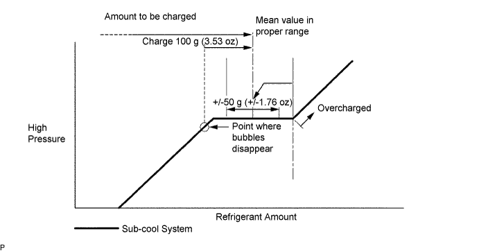
Note
-
Do not operate the cooler compressor before charging refrigerant as the cooler compressor will not work properly without any refrigerant, and will overheat.
-
Approximately 200 g (7.05 oz) of refrigerant may need to be charged after bubbles disappear. The refrigerant amount should be checked by measuring its quantity, and not with the sight glass.
-
-
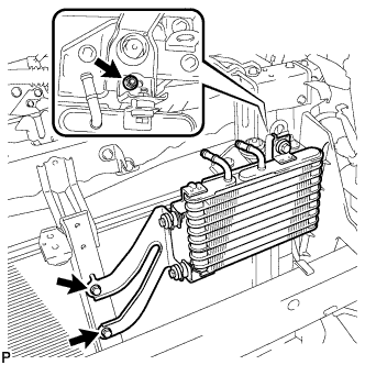
INSTALL OIL COOLER ASSEMBLY (w/ Air Cooled Transmission Oil Cooler)
-
Install the oil cooler with the 2 bolts and nut.
- Torque:
- 5.5 N*m { 56 kgf*cm, 49 in.*lbf }
-
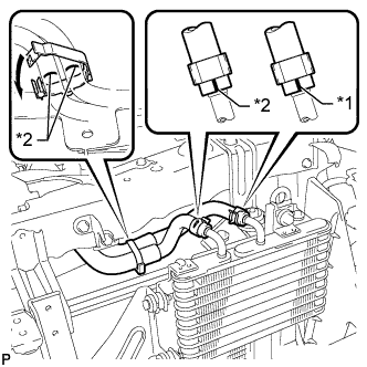
Text in Illustration *1 Blue Paint Mark *2 White Paint Mark Connect the transmission oil cooler hose and No. 3 oil cooler outlet hose to the oil cooler.
Note
Make sure the pinching portion of each clip is facing the direction shown in the illustration and the paint marks are aligned as shown in the illustration.
-
Align the 2 flexible hose clamps with the paint marks on the 2 hoses, pass the 2 hoses through the clamps and close the clamps.
-
-
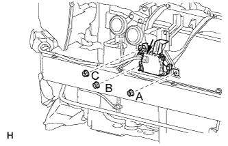
INSTALL MILLIMETER WAVE RADAR SENSOR ASSEMBLY (w/ Dynamic Radar Cruise Control System)
-
Install the sensor with the 3 nuts in the alphabetical order.
- Torque:
- 5.5 N*m { 56 kgf*cm, 49 in.*lbf }
-
Connect the sensor connector.
-
-
INSTALL FRONT BUMPER COVER
-
Install the front bumper cover Click here.
-
-
WARM UP ENGINE
-
Warm up the engine at less than 1850 rpm for 2 minutes or more after charging the refrigerant.
Note
Be sure to warm up the compressor when turning the A/C switch on after removing and installing the cooler refrigerant lines (including the compressor) to prevent damage to the compressor.
-
-
CHECK FOR REFRIGERANT GAS LEAK
-
After recharging the refrigerant gas, check for refrigerant gas leakage using a halogen leak detector.
-
Perform the operation observing the following instructions:
-
Stop the engine.
-
Secure good ventilation (the halogen leak detector may react to volatile gases other than refrigerant, such as evaporated gasoline or exhaust gas).
-
Repeat the test 2 or 3 times.
-
Make sure that some refrigerant remains in the refrigeration system.
Tech Tips
When the compressor is off: approximately 392 to 588 kPa (4.0 to 6.0 kgf/cm2, 57 to 85 psi).
-
-
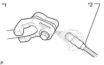
Text in Illustration *1 Check for Leakage *2 Halogen Leak Detector Using a halogen leak detector, check the refrigerant line for leakage.
-
If a gas leak is not detected from the drain hose, remove the blower motor control (blower resistor) from the cooling unit. Insert the halogen leak detector sensor into the unit and check for gas leakage.
-
Disconnect the pressure switch connector and wait for approximately 20 minutes. Bring the halogen leak detector close to the pressure switch and check for gas leakage.
-