AIR CONDITIONING SYSTEM (for Manual Air Conditioning System) Headlight Signal Circuit
DESCRIPTION
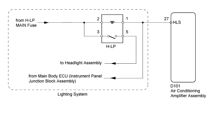
The air conditioning amplifier assembly receives the headlight illumination signal and uses the signal to judge electric load conditions. The electric load signal is one element of PTC heater control.
WIRING DIAGRAM
INSPECTION PROCEDURE
PROCEDURE
-
CHECK HEADLIGHT (OPERATION)
-
Check if the headlight comes on when the light control switch is turned to the headlight.
OK Headlight comes on.
NG 
GO TO LIGHTING SYSTEM Click here
OK 
-
-
CHECK HARNESS AND CONNECTOR (HEADLIGHT SIGNAL)
-
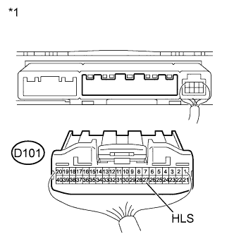
Text in Illustration *1 Rear view of wire harness connector
(to Air Conditioning Amplifier Assembly)
Disconnect the D101 amplifier connector.
-
Measure the voltage according to the value(s) in the table below.
Standard Voltage Tester Connection Condition Specified Condition D101-27 (HLS) - Body ground
-
Engine started
-
Headlight dimmer switch: off
11 to 14 V D101-27 (HLS) - Body ground
-
Engine started
-
Headlight dimmer switch: on
Below 1 V -
NG
REPAIR OR REPLACE HARNESS OR CONNECTOR
OK 
PROCEED TO NEXT SUSPECTED AREA SHOWN IN PROBLEM SYMPTOMS TABLE Click here
-