COMBUSTION TYPE POWER HEATER SYSTEM Power Heater Alternator Circuit
DESCRIPTION
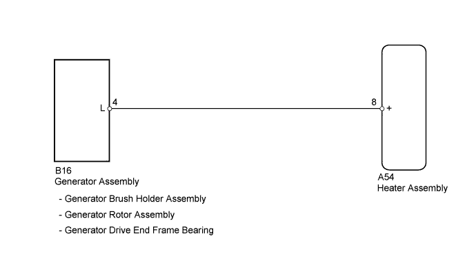
The ECU receives engine operation signals from the L terminal of the generator assembly. If this circuit is open, the ECU will determine that the engine operation signals indicate that the engine is running. If this circuit is shorted, the ECU will determine that the engine operation signals indicate that the engine is stopped, and the heater assembly will not operate.
WIRING DIAGRAM
INSPECTION PROCEDURE
PROCEDURE
-
INSPECT GENERATOR BRUSH HOLDER ASSEMBLY
-
Remove the generator assembly.
-
for 1AD-FTV Click here
-
for 2AD-FHV Click here
-
for 2AD-FTV Click here
-
-
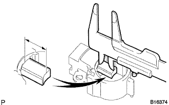
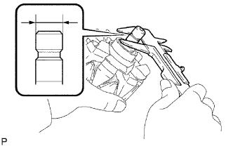
Using a vernier caliper, measure the brush length.
Standard exposed length 10.5 to 11.5 mm (0.374 to 0.453 in.) Minimum exposed length 4.5 mm (0.177 in.) Result Result Proceed to OK A NG (for 1AD-FTV) B NG (for 2AD-FHV) C NG (for 2AD-FTV) D
B 
REPLACE GENERATOR BRUSH HOLDER ASSEMBLY Click here
C
REPLACE GENERATOR BRUSH HOLDER ASSEMBLY Click here
D
REPLACE GENERATOR BRUSH HOLDER ASSEMBLY Click here
A 
-
-
INSPECT GENERATOR ROTOR ASSEMBLY
-
Remove the generator assembly.
-
for 1AD-FTV Click here
-
for 2AD-FHV Click here
-
for 2AD-FTV Click here
-
-
Check the rotor for an open circuit.
-
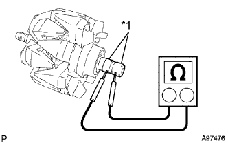
Text in Illustration *1 Slip Ring Measure the resistance according to the value(s) in the table below.
Standard Resistance Tester Connection Condition Specified Condition Slip ring - Slip ring 20°C (68°F) 2.3 to 2.7 Ω
-
-
Check if the rotor is grounded.
-
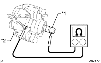
Text in Illustration *1 Slip Ring *2 Rotor Core Measure the resistance according to the value(s) in the table below.
Standard Resistance Tester Connection Condition Specified Condition Slip ring - Rotor Always 10 kΩ or higher
-
-
Check that the slip rings are not rough or scored.
-
Using a vernier caliper, measure the slip ring diameter.
Standard diameter 14.2 to 14.4 mm (0.559 to 0.567 in.) Minimum diameter 14.0 mm (0.551 in.) -
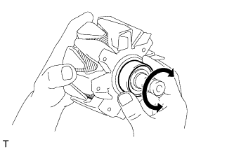
Check that the generator rotor bearing is not rough or worn, and that it rotates smoothly.
Result Result Proceed to The results are as specified A The results are not as specified (for 1AD-FTV) B The results are not as specified (for 2AD-FHV) C The results are not as specified (for 2AD-FTV) D
B
REPLACE GENERATOR ROTOR ASSEMBLY Click here
C
REPLACE GENERATOR ROTOR ASSEMBLY Click here
D
REPLACE GENERATOR ROTOR ASSEMBLY Click here
A
-
-
INSPECT GENERATOR DRIVE END FRAME BEARING
-
Remove the generator assembly.
-
for 1AD-FTV Click here
-
for 2AD-FHV Click here
-
for 2AD-FTV Click here
-
-
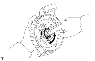
Check that the generator drive end frame bearing is not rough or worn, and that it rotates smoothly.
OK The generator drive end frame bearing is normal. Result Result Proceed to OK A NG (for 1AD-FTV) B NG (for 2AD-FHV) C NG (for 2AD-FTV) D
B
REPLACE GENERATOR DRIVE END FRAME BEARING Click here
C
REPLACE GENERATOR DRIVE END FRAME BEARING Click here
D
REPLACE GENERATOR DRIVE END FRAME BEARING Click here
A
-
-
INSPECT GENERATOR PULLEY
-
Remove the generator assembly.
-
for 1AD-FTV Click here
-
for 2AD-FHV Click here
-
for 2AD-FTV Click here
-
-
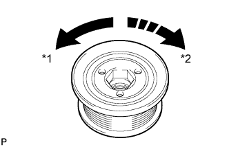
Text in Illustration *1 Free *2 Lock Hold the center of the generator pulley and confirm that the outer ring turns counterclockwise and does not turn clockwise.
OK The generator pulley is normal. Result Result Proceed to OK A NG (for 1AD-FTV) B NG (for 2AD-FHV) C NG (for 2AD-FTV) D
B
REPLACE GENERATOR PULLEY Click here
C
REPLACE GENERATOR PULLEY Click here
D
REPLACE GENERATOR PULLEY Click here
A
-
-
CHECK HARNESS AND CONNECTOR (HEATER ASSEMBLY - GENERATOR)
-
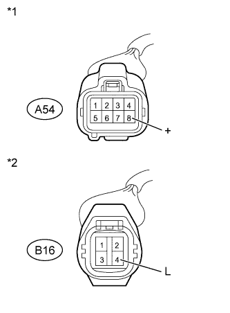
Text in Illustration *1 Front view of wire harness connector
(to Heater Assembly)
*2 Front view of wire harness connector
(to Generator Assembly)
Disconnect the A54 heater assembly connector.
-
Measure the voltage according to the value(s) in the table below.
Standard Voltage Tester Connection Condition Specified Condition A54-8 (+) - Body ground Engine running
(Generator operating)
11 to 14 V -
Disconnect the B16 generator assembly connector.
-
Measure the resistance according to the value(s) in the table below.
Standard Resistance Tester Connection Condition Specified Condition A54-8 (+) - B16-4 (L) Always Below 1 Ω A54-8 (+) - Body ground Always 10 kΩ or higher
NG
REPAIR OR REPLACE HARNESS OR CONNECTOR
OK 
PROCEED TO NEXT SUSPECTED AREA SHOWN IN PROBLEM SYMPTOMS TABLE Click here
-