AIR CONDITIONING SYSTEM (for Manual Air Conditioning System) SYSTEM DESCRIPTION

-
GENERAL
-
The air conditioning system has the following features:
-
The air conditioning amplifier controls the operation of parts, such as the A/C compressor, automatically in accordance with the operating conditions of the air conditioning system.
-
The Positive Temperature Coefficient (PTC) heater system contains a PTC heater that heats the air that has passed through the heater core to ensure proper heater performance. The PTC heater is applicable and automatically controllable to 495 W, 330 W and 165 W, because of its self-regulating characteristics.
-
A combustion type power heater is available as optional equipment to provide comfortable heater performance in cold areas.
-
A compact, lightweight, and highly efficient straight flow (full-path flow) aluminum heater core is used.
-
The micro dust and pollen filter control is used to remove pollen in the air around the upper areas of the driver and front passenger seats.
-
The air conditioning amplifier assembly is equipped with a self diagnosis function. If there is a malfunction in the system, it stores DTCs (Diagnostic Trouble Codes) in its memory.
-
-
-
MODE POSITION AND DAMPER OPERATION
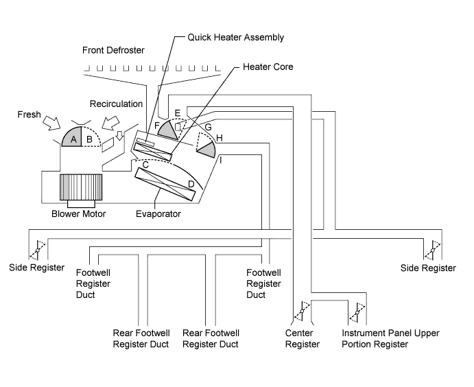
Function of Main Damper Control Damper Operation Position Damper Position Operation Air Inlet Control Damper Fresh A Brings in fresh air. Recirculation B Recirculates internal air. Air Mix Control Damper Max Cool to Max Hot C - D Varies the mixture of cold air and hot air in order to regulate the temperature continuously from hot to cool. Mode Control Damper 
Face
F, I Air blows out of the center registers, instrument panel upper portion register, and side registers. 
Bi-level
F, H Air blows out of the center registers, instrument panel upper portion register, side registers, and front and rear footwell register ducts. 
Foot
E, G Air blows out of the front and rear footwell register ducts and side registers.
In addition, air blows out slightly from the front defroster.

Foot/Def
E, H Defrosts the windshield through the front defroster and side registers, while air is also blown out from the front and rear footwell register ducts.
In addition, air blows out slightly from the front defroster.

Def
E, I Defrosts the windshield through the front defroster and side registers. -
AIR OUTLETS AND AIRFLOW VOLUME
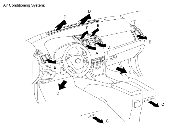
INDICATION
(MODE)
Center Register Side Register Front and Rear Footwell Register Defroster Instrument Panel Upper Portion Register A B C D E Face

- - Bi-level

- Foot
- 

- Foot/Def
- - Def
- - - Tech Tips
-
The size of the circle indicates the proportion of airflow volume.
-
The same system is used for LHD and RHD vehicles.
-