EXHAUST MANIFOLD W/ TURBOCHARGER INSTALLATION

-
INSTALL EXHAUST MANIFOLD AND TURBOCHARGER SUB-ASSEMBLY
-
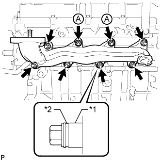
Text in Illustration *1 Collar *2 Groove Temporarily install a new gasket, and the exhaust manifold and 2 collars with the 2 nuts labeled A. Tighten the nuts until the mating surface of the exhaust manifold contacts the cylinder head.
-
Temporarily install the 6 collars with the 6 nuts.
Tech Tips
-
When installing the collars, pay attention to the mounting orientation. The ring groove of the collar should be on the outside. Refer to the illustration.
-
Do not fully tighten the nuts as doing so may result in misalignment of the exhaust manifold.
-
-
Install a new gasket and the turbocharger with 3 new nuts.
- Torque:
- 60 N*m { 612 kgf*cm, 44 ft.*lbf }
-
Connect the vacuum hose.
-
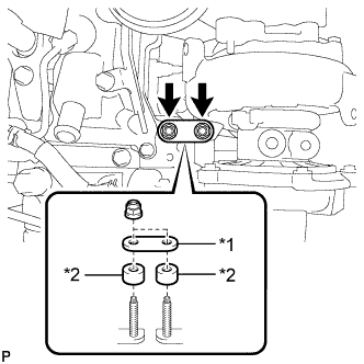
Text in Illustration *1 New Turbocharger Stay *2 Collar Install the 2 collars and a new turbocharger stay with the 2 nuts.
- Torque:
- 36 N*m { 367 kgf*cm, 27 ft.*lbf }
Note
Do not reuse the turbocharger stay.
-
Tighten the 8 nuts of the exhaust manifold.
- Torque:
- 47 N*m { 479 kgf*cm, 35 ft.*lbf }
-
-
INSTALL NO. 2 TURBO OIL PIPE
-
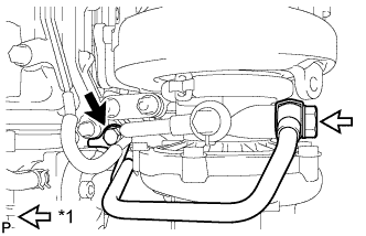
Install the No. 2 turbo oil pipe and 2 new gaskets with the 2 union bolts.
- Torque:
- 35 N*m { 357 kgf*cm, 26 ft.*lbf }
-
Connect the vacuum hose.
-
-
INSTALL NO. 2 TURBO WATER PIPE SUB-ASSEMBLY (for Manual Transaxle)
-
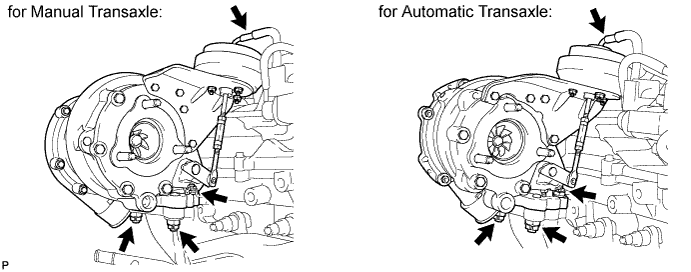
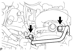
Text in Illustration *1 Union Bolt Install the No. 2 turbo water pipe and a new gasket with the union bolt and bolt.
- Torque:
- for bolt
- 28 N*m { 286 kgf*cm, 21 ft.*lbf }
- for union bolt
- 38 N*m { 387 kgf*cm, 28 ft.*lbf }
-
-
INSTALL NO. 5 WATER BY-PASS PIPE (for Automatic Transaxle)
-
Install the No. 5 water by-pass pipe with the 2 bolts.
- Torque:
- 28 N*m { 286 kgf*cm, 21 ft.*lbf }
-
-
CONNECT NO. 3 WATER BY-PASS HOSE
-
INSTALL NO. 1 TURBO WATER PIPE SUB-ASSEMBLY (for Manual Transaxle)
-
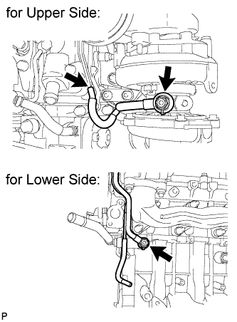
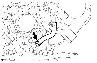
Install the No. 1 turbo water pipe and a new gasket with the union bolt.
- Torque:
- 38 N*m { 387 kgf*cm, 28 ft.*lbf }
Note
Make sure there is no coolant on the union bolt.
-
-
INSTALL NO. 1 TURBO INSULATOR
-
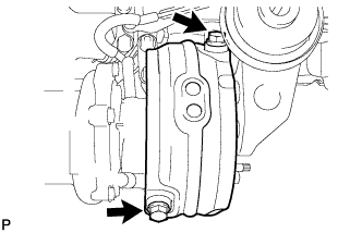
Install the No. 1 turbo insulator with the 2 bolts.
- Torque:
- 21 N*m { 209 kgf*cm, 15 ft.*lbf }
-
-
INSTALL TURBO OIL OUTLET PIPE
-
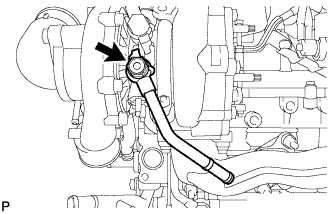
Install 2 new gaskets to the turbo oil outlet pipe.
-
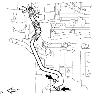
Text in Illustration *1 Nut Install the turbo oil outlet pipe with the 2 bolts and 2 nuts.
- Torque:
- 11 N*m { 112 kgf*cm, 8 ft.*lbf }
-
-
INSTALL EGR COOLER WITH PIPE ASSEMBLY
-
Install the EGR cooler with pipe assembly Click here.
-