FUEL SENDER GAUGE ASSEMBLY REMOVAL

-
REMOVE REAR SEAT CUSHION ASSEMBLY
-
for Sedan: Click here
-
for Wagon: Click here
-
-
REMOVE REAR FLOOR SERVICE HOLE COVER
-
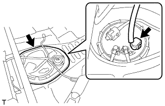
Remove the butyl tape and service hole cover.
-
Disconnect the fuel sender gauge connector.
-
-
DISCONNECT FUEL TANK MAIN TUBE SUB-ASSEMBLY
-
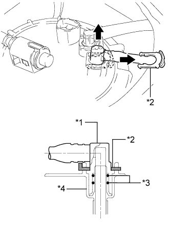
Text in Illustration *1 Fuel Tube Joint *2 Tube Joint Clip *3 O-Ring *4 Fuel Tank Vent Tube Remove the tube joint clip and pull out the fuel tank main tube.
Note
-
Remove any dirt and foreign matter on the fuel tube joint before performing this step.
-
Do not scratches or allow any foreign matter to adhere to the parts when disconnecting them as the fuel tube joint contains the O-rings that seal the plug.
-
Perform this step by hand. Do not use any tools.
-
Do not forcibly bend or twist the nylon tube.
-
Protect the disconnected part by covering it with a plastic bag after disconnecting the fuel tube.
-
-
-
DISCONNECT FUEL RETURN TUBE SUB-ASSEMBLY
-
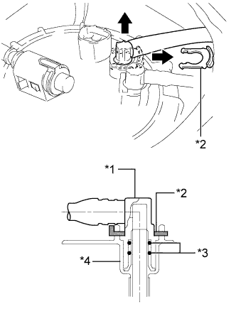
Text in Illustration *1 Fuel Tube Joint *2 Tube Joint Clip *3 O-Ring *4 Fuel Tank Vent Tube Remove the tube joint clip and pull out the fuel return tube.
Note
-
Remove any dirt and foreign matter on the fuel tube joint before performing this step.
-
Do not scratches or allow any foreign matter to adhere to the parts when disconnecting them as the fuel tube joint contains the O-rings that seal the plug.
-
Perform this step by hand. Do not use any tools.
-
Do not forcibly bend, twist or turn the nylon tube.
-
Protect the disconnected part by covering it with a plastic bag after disconnecting the fuel tube.
-
-
-
REMOVE TANK SUCTION TUBE SUPPORT
-
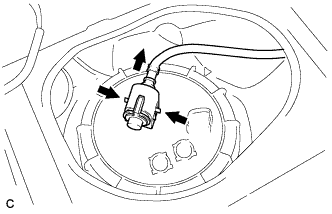
Press on the tabs from both sides of the tube.
-
Pull the tube in the direction indicated by the arrow in the illustration.
-
Detach the 2 claws and remove the suction tube support.
-
-
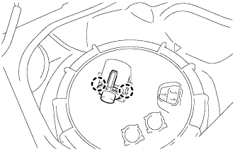
REMOVE FUEL PUMP GAUGE RETAINER
-
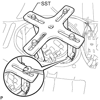
Temporarily install SST (plate and 4 claws) to the fuel pump gauge retainer.
- SST
- 09808-14030
- 09808-01070
Tech Tips
-
Be sure to use 4 SST (claws) as shown in the illustration.
-
Engage SST (claws) securely with the fuel pump gauge retainer ribs to secure SST.
-
While pressing SST (claws) against the fuel pump gauge retainer ribs securely, install the 4 bolts.
Tech Tips
Install SST while pressing SST (claws) against the fuel pump gauge retainer (towards the center of SST).
-
Install SST (handle).
-
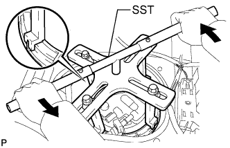
Lightly press down on SST to prevent it from separating from the fuel pump gauge retainer. While pressing SST, rotate the handle slowly to loosen the fuel pump gauge retainer.
- SST
- 09808-14030
- 09808-01070
Text in Illustration 
Turn Note
-
Do not use any tools other than specified in this operation. Damage to the fuel pump gauge retainer or the fuel tank may result.
-
Do not press down on SST excessively as this may make the fuel pump gauge retainer hard to rotate, and may damage components.
-
Make sure to rotate SST (handle) horizontally. If SST (handle) is rotated at an angle, SST may come off.
-
Do not spin SST too fast or use an impact wrench as this may result in damage to components.
-
If SST comes off of the fuel pump gauge retainer, loosen SST (bolts) and reinstall SST.
Tech Tips
The tips of SST (claws) can be fitted onto the ribs of the fuel pump gauge retainer.
-
Remove the fuel pump gauge retainer while holding the fuel suction with pump assembly by hand.
-
-
REMOVE FUEL TANK VENT TUBE SUB-ASSEMBLY
-
Remove the fuel tank vent tube from the fuel tank.
Note
Make sure that the fuel sender gauge arm does not bend.
-
Text in Illustration *1 Gasket Remove the gasket from the fuel tank.
-
-
REMOVE FUEL SENDER GAUGE ASSEMBLY
-
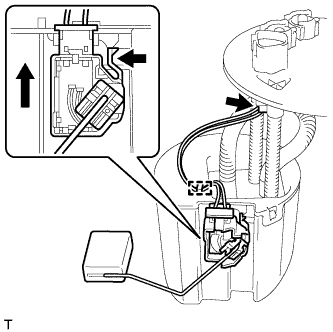
Disconnect the sender gauge connector.
-
Detach the wire harness clamp.
Note
Do not damage the wire harness.
-
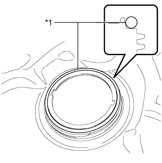
Release the lock as shown in the illustration and slide the fuel sender gauge to remove it.
-