CYLINDER BLOCK REASSEMBLY

Note
Before performing these installation procedures, sufficiently clean and remove any foreign matter from the cylinder block, connecting rod and other parts.
-
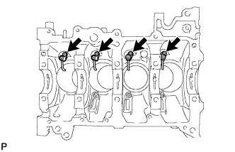
INSTALL OIL REFLECTOR PLATE
-
Using a 5 mm hexagon wrench, install the 3 oil reflector plates with the 3 bolts.
- Torque:
- 9.0 N*m { 92 kgf*cm, 80 in.*lbf }
-
-
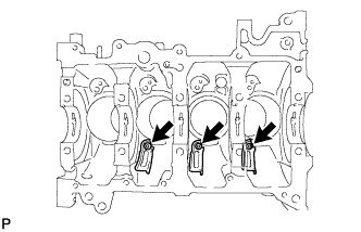
INSTALL NO. 1 OIL NOZZLE SUB-ASSEMBLY
-
Using a 5 mm hexagon wrench, install the 4 oil nozzles with the 4 bolts.
- Torque:
- 9.0 N*m { 92 kgf*cm, 80 in.*lbf }
-
-
INSTALL NO. 1 CRANKSHAFT POSITION SENSOR PLATE
-
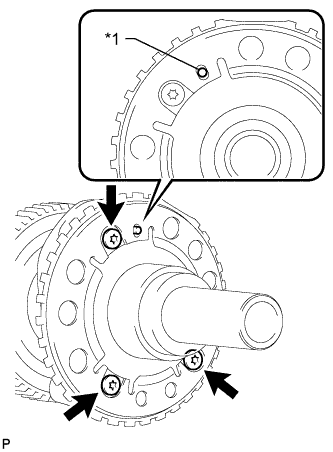
Text in Illustration *1 Straight Pin Install the sensor plate by fitting the straight pin of the crankshaft into the hole on the sensor plate.
-
Using a T30 "TORX" socket wrench, install the 3 bolts.
- Torque:
- 11 N*m { 107 kgf*cm, 8 ft.*lbf }
Note
Make sure that the sensor plate is not slanted.
-
-
INSTALL PISTON WITH PIN SUB-ASSEMBLY
-
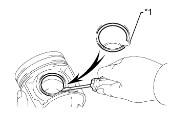
Text in Illustration *1 Service Hole Using a screwdriver, install a new snap ring on one side of the piston pin hole.
Tech Tips
Be sure that the end gap of the snap ring is not aligned with the service hole cutout portion of the piston.
-
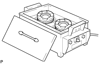
Gradually heat the piston to approximately 80 to 90°C (176 to 194°F).
-
Coat the piston pin with engine oil.
-
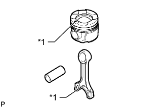
Text in Illustration *1 Front Mark Align the front marks of the piston and connecting rod, install the connecting rod to the piston and push in the piston pin with your thumb.
Tech Tips
The piston and pin are a matched set.
-
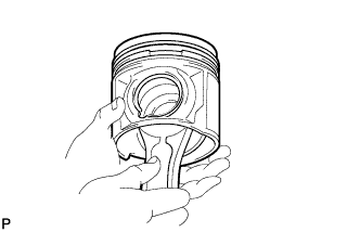
Check the fitting condition between the piston and piston pin by trying to move the piston back and forth on the piston pin.
-
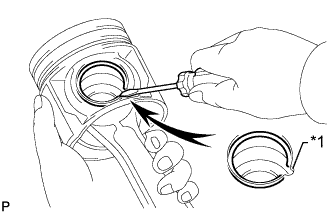
Text in Illustration *1 Service Hole Using a screwdriver, install a new snap ring at the other end of the piston pin hole.
Tech Tips
Be sure that the end gap of the snap ring is not aligned with the service hole cutout portion of the piston.
-
-
INSTALL PISTON RING SET
-
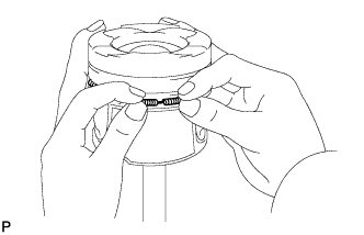
Install the oil ring expander by hand.
-
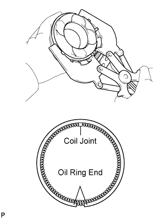
Using a piston ring expander, install the oil ring rail.
Tech Tips
Face the end gap of the oil ring in the opposite direction of the coil joint.
-
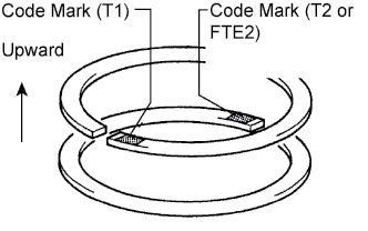
Using a piston ring expander, install the No. 1 and No. 2 compression rings so that the code marks are positioned as shown in the illustration.
Code Mark Ring Code Mark No. 1 1T No. 2 T2 or FTE2 Tech Tips
-
Install the No. 1 compression ring with the code mark facing upward.
-
Install the No. 2 compression ring with the code mark facing upward.
-
-
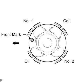
Position the piston rings so that the ring ends are as shown in the illustration.
Note
Do not align the ring ends.
-
-
INSTALL CONNECTING ROD BEARING
Note
Apply oil to the inner surface of each bearing (the surface which contacts the crankshaft), but not to the outer surface (the surface which contacts the connecting rod or connecting rod cap).
-
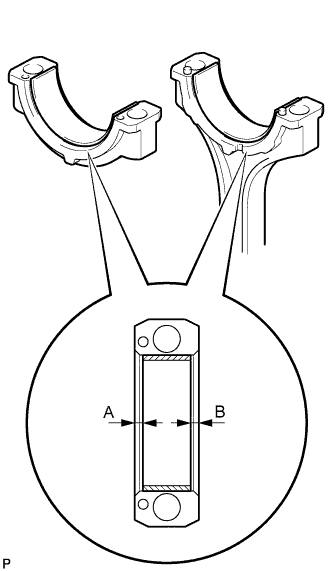
Install the bearings to the connecting rod and connecting rod cap.
-
Using a vernier caliper, measure the distance between the bearing cap edge and bearing edge.
Dimension A - B or B - A 0 to 0.7 mm (0 to 0.0276 in.) Note
Clean the backside of the bearing and the bearing surface of the connecting rod.
-
-
INSTALL CRANKSHAFT BEARING
Note
-
Apply oil to the inner surface of each bearing (the surface which contacts the crankshaft), but not to the outer surface (the surface which contacts the bearing cap or cylinder block).
-
When replacing a bearing, also replace the corresponding upper or lower bearing.
-
Clean each main journal and bearing.
-
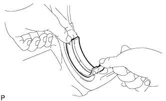
Align the bearing claw with the claw groove of the cylinder block, and push in the 5 upper crankshaft bearings to install them.
Note
-
Clean the contact surface of the bearing and cylinder block.
-
Apply oil to the inner surface of each bearing (the surface which contacts the crankshaft), but not to the outer surface (the surface which contacts the cylinder block).
-
Make sure both sides of the oil groove in the cylinder block are visible through the oil feed holes in the bearing. Make sure the amount visible on each side of the holes is equal.
-
-
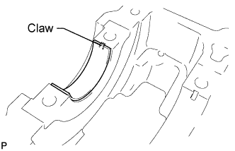
Align the bearing claw with the claw groove of the bearing cap, and push in the 5 lower crankshaft bearings to install them.
Note
-
Clean the contact surface of the bearing and crankshaft bearing cap.
-
Apply oil to the inner surface of each bearing (the surface which contacts the crankshaft), but not to the outer surface (the surface which contacts the bearing cap).
-
-
-
INSTALL UPPER CRANKSHAFT THRUST WASHER
Note
When replacing a thrust washer, replace both thrust washers together as a set.
-
Apply engine oil to the crankshaft bearings, then place the crankshaft on the cylinder block.
-
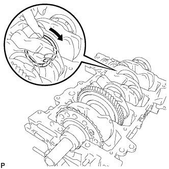
Push the crankshaft in one direction and install one thrust washer to the No. 4 journal position with the oil groove facing outward.
-
Push the crankshaft in the opposite direction and install the other thrust washer to the No. 4 journal position with the oil groove facing outward.
-
-
INSTALL CRANKSHAFT
-
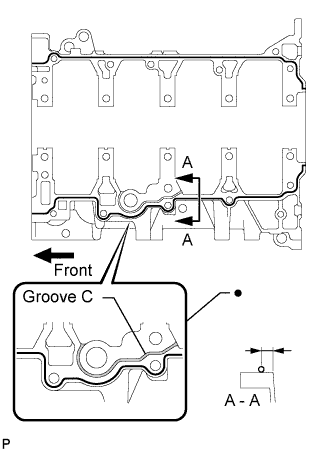
Apply seal packing in a continuous line as shown in the illustration.
Seal packing Toyota Genuine Seal Packing Black, Three Bond 1207B or equivalent Seal diameter 2.0 to 4.0 mm (0.0787 to 0.157 in.) Note
-
Remove any oil from the contact surface.
-
Install the crankshaft bearing cap within 3 minutes after applying seal packing.
-
Do not start the engine for at least 4 hours after installing.
-
Do not overlap seal packing in area ● in the illustration.
-
Do not apply seal packing in groove C.
-
-
Apply engine oil to the crankshaft bearings, then place the crankshaft bearing cap on the cylinder block.
-
Temporarily install the crankshaft bearing cap bolts.
Tech Tips
The main bearing cap bolts are tightened in 2 progressive steps.
-
Step 1:
-
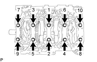
Uniformly tighten the 10 main bearing cap bolts in several steps, in the sequence shown in the illustration.
- Torque:
- 60 N*m { 612 kgf*cm, 44 ft.*lbf }
Tech Tips
If any of the main bearing cap bolts does not meet the torque specification, replace the main bearing cap bolt.
-
-
Step 2:
-
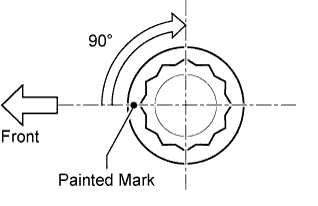
Mark the front of the bearing cap bolts with paint.
-
Tighten the bearing cap bolts by 90°.
-
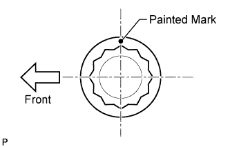
Check that the painted marks are now at a 90° angle to the front.
-
-
Check that the crankshaft turns smoothly.
-
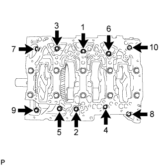
Install and uniformly tighten the 10 bolts in several passes in the sequence shown.
- Torque:
- 18 N*m { 184 kgf*cm, 13 ft.*lbf }
-
-
INSTALL PISTON SUB-ASSEMBLY WITH CONNECTING ROD
-
Apply engine oil to the cylinder walls, the pistons, and the surfaces of the connecting rod bearings.
-

Check the positions of the piston ring ends.
Note
Do not align the ring ends.
-
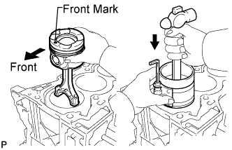
Using a hammer handle and piston ring compressor, press a piston and connecting rod assembly into each cylinder with the front mark of the piston facing forward.
-
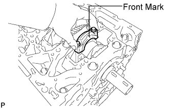
Install the connecting rod cap so that its front mark (protrusion) is facing the correct direction.
Note
-
Make sure that the front mark of the connecting rod cap is facing forward.
-
Match the numbered connecting rod cap with the connecting rod.
-
-
Apply a light coat of engine oil to the threads and under the heads of the connecting rod cap bolts.
-
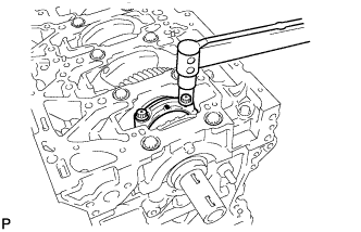
Install and alternately tighten the bolts of the connecting rod cap in several steps.
- Torque:
- 40 N*m { 408 kgf*cm, 30 ft.*lbf }
-
Mark the front side of each connecting cap bolt with paint.
-
Tighten the cap bolts by 90°.
-
Check that the painted marks are now at a 90° angle to the front.
-
Check that the crankshaft turns smoothly.
-
-
INSPECT CONNECTING ROD THRUST CLEARANCE
-
Install the piston with pin, piston ring set and connecting rod bearing Click here.
-
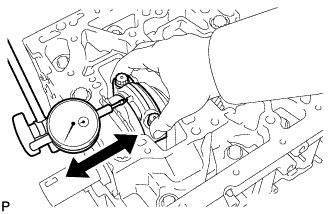
Using a dial indicator, measure the thrust clearance while moving the connecting rod back and forth.
Standard thrust clearance 0.10 to 0.45 mm (0.00394 to 0.0177 in.) Maximum thrust clearance 0.55 mm (0.0217 in.) If the thrust clearance is more than the maximum, replace one or more connecting rods as necessary. If necessary, replace the crankshaft.
-
Remove the connecting rod bearing, piston ring set and piston with pin Click here.
-