ENGINE UNIT REASSEMBLY

Note
-
When replacing the injectors (including shuffling the injectors between the cylinders), common rail, intake manifold or cylinder head, it is necessary to replace the injection pipes with new ones.
-
When replacing the fuel supply pump, common rail, intake manifold or cylinder head, it is necessary to replace the fuel inlet pipe with a new one.
-
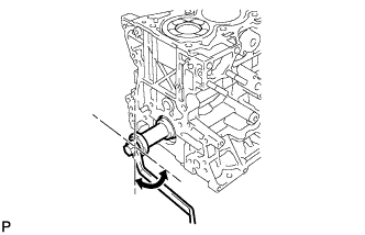
INSTALL CYLINDER BLOCK DRAIN COCK PLUG
-
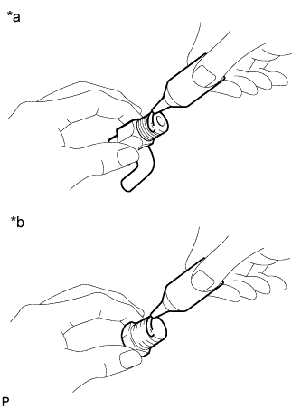
Text in Illustration *a Type A *b Type B Apply adhesive to the cylinder block drain cock plug.
Seal packing Toyota Genuine Seal Packing 1282B, Three Bond 1282B or equivalent -
Type A:
-
Install the cylinder block drain cock plug.
- Torque:
- 20 N*m { 204 kgf*cm, 15 ft.*lbf }
Tech Tips
If the cock is not within the range shown in the illustration after installing it, perform the following step.
-
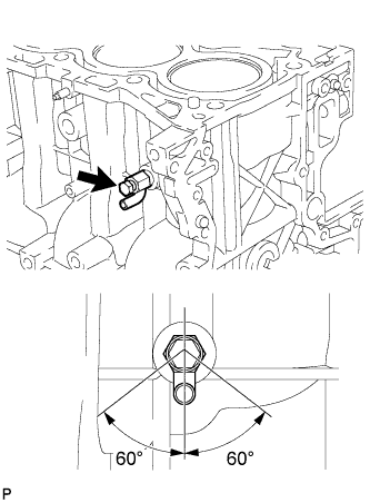
Within one full rotation, tighten the cylinder block drain cock plug so that it is within the range shown in the illustration.
- Torque:
- 80 N*m { 816 kgf*cm, 59 ft.*lbf, or less }
Note
Do not loosen the cylinder block drain cock plug to adjust it. If an adjustment is necessary, remove the cock and reinstall it.
-
-
Type B:
-
Install the cylinder block drain cock plug.
- Torque:
- 25 N*m { 255 kgf*cm, 18 ft.*lbf }
-
-
-
INSTALL ENGINE BALANCER ASSEMBLY
-
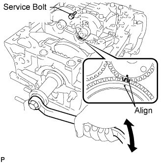
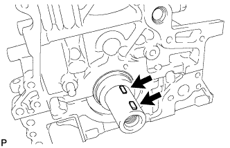
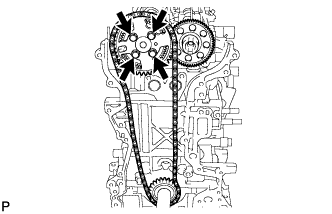
Turn the crankshaft with a wrench to align the timing mark of the drive gear with that of the driven gear (1 dot mark each), and then mesh the gears and install the engine balancer to the engine.
-
Temporarily install the engine balancer bolts.
Tech Tips
The engine balancer bolts are tightened in 2 progressive steps.
-
Step 1
-
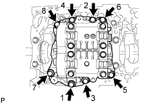
Uniformly tighten the 8 bolts in several passes in the sequence shown in the illustration.
- Torque:
- 50 N*m { 510 kgf*cm, 37 ft.*lbf }
-
-
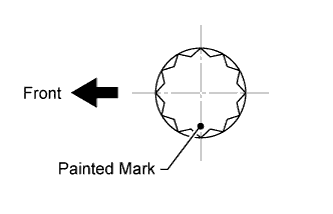
Step 2
-
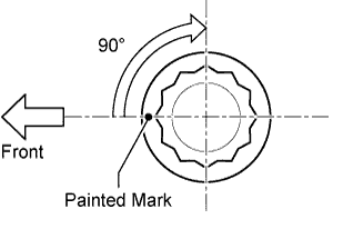
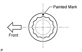
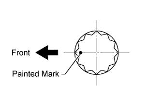
Mark the front of the engine balancer bolts with paint.
-
Tighten the engine balancer bolts by 90°.
-
Check that the painted marks are now at a 90° angle to the front.
-
-
Remove the service bolt from the engine balancer.
-
-
INSTALL OIL BAFFLE PLATE
-
Install the oil baffle plate with the 2 bolts.
- Torque:
- 9.0 N*m { 92 kgf*cm, 80 in.*lbf }
-
-
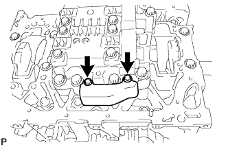
INSTALL REAR CRANKSHAFT OIL SEAL
-
Coat the lip of a new oil seal with MP grease.
-
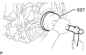
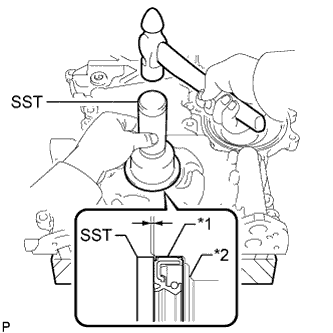
Using SST, tap in the oil seal until its surface is flush with the oil seal retainer edge.
- SST
- 09223-56010
Note
-
Keep the lip free from foreign matter.
-
Do not tap the oil seal at an angle.
-
-
SELECT CYLINDER HEAD GASKET
-
Check the piston protrusions for each cylinder.
-
Clean the cylinder block with solvent.
-
Set the piston of the cylinder to be measured to slightly before TDC.
-
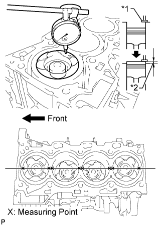
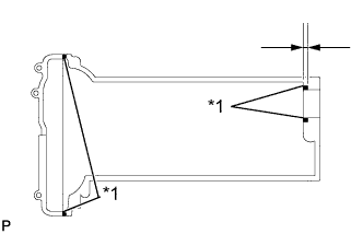
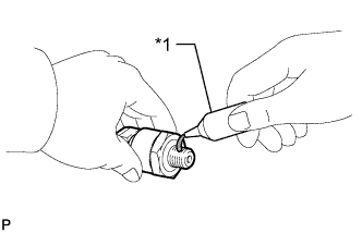
Text in Illustration *1 Measuring Tip *2 Protrusion Place a dial indicator on the cylinder block, and set the measuring tip as shown in the illustration.
-
Set the dial indicator at 0 mm (0 in.).
Tech Tips
Make sure that the measuring tip is perpendicular to the cylinder block gasket surface and piston head when taking the measurements.
-
Find where the piston head protrudes most by slowly turning the crankshaft clockwise and counterclockwise.
-
Measure each cylinder at 2 places as shown in the illustration, making a total of 8 measurements.
-
For the piston protrusion value of each cylinder, use the average of the 2 measurements of each cylinder.
Standard piston protrusion 0.300 to 0.560 mm (0.0118 to 0.0220 in.) If the protrusion is not as specified, remove the piston and connecting rod and reinstall it.
-
-
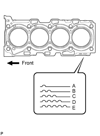
Select a new cylinder head gasket.
Tech Tips
Cylinder head gaskets are marked A, B, C, D or E accordingly.
New Installed Cylinder Head Gasket Thickness Cutout Mark Specified Condition A 1.00 to 1.10 mm (0.0394 to 0.0433 in.) B 1.05 to 1.15 mm (0.0413 to 0.0453 in.) C 1.10 to 1.20 mm (0.0433 to 0.0472 in.) D 1.15 to 1.25 mm (0.0453 to 0.0492 in.) E 1.20 to 1.30 mm (0.0472 to 0.0512 in.)
-
Select the largest piston protrusion value from the measurements and then select a new appropriate gasket according to the table below.
Piston Protrusion Specified Condition Gasket Size 0.300 to 0.355 mm (0.0118 to 0.0140 in.) Use A 0.355 to 0.405 mm (0.0140 to 0.0159 in.) Use B 0.405 to 0.455 mm (0.0159 to 0.0179 in.) Use C 0.455 to 0.505 mm (0.0179 to 0.0199 in.) Use D 0.505 to 0.560 mm (0.0199 to 0.0220 in.) Use E
-
-
-
INSTALL CYLINDER HEAD GASKET
-
INSTALL CYLINDER HEAD SUB-ASSEMBLY
-
Using the crankshaft pulley bolt, set the No. 1 cylinder to 90° BTDC/compression.
-
Place the cylinder head gasket in position on the cylinder block.
-
Place the cylinder head on the cylinder block.
Note
Be careful of the installation direction.
-
Apply a light coat of engine oil to the threads and under the heads of the cylinder head bolts.
-
Temporarily install the cylinder head bolts.
Tech Tips
If any bolt is broken or deformed, replace it.
-
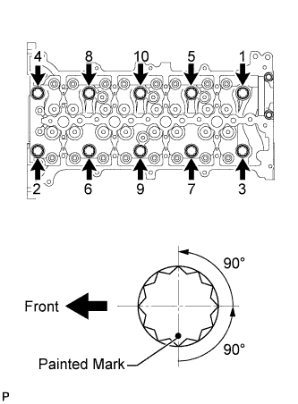
Step 1:
Tech Tips
For new bolts, perform steps 1 to 3. For used bolts, perform only step 1.
-
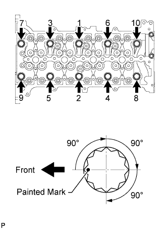
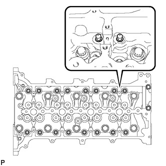
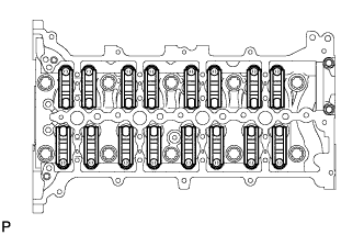
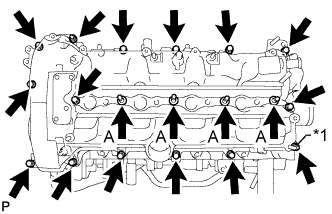
Uniformly tighten the 10 cylinder head bolts in several steps in the sequence shown in the illustration.
- Torque:
- 50 N*m { 510 kgf*cm, 37 ft.*lbf }
Tech Tips
If any one of the cylinder head bolts does not meet the torque specification, replace the cylinder head bolt.
-
Mark the front of the cylinder head bolts with paint.
-
Tighten the cylinder head bolts by 90° in the sequence shown in the illustration.
-
Perform the step above twice.
-
Check that the painted marks are positioned as shown in the illustration.
-
-
Step 2:
-
Loosen the cylinder head bolts by 90° in the sequence shown in the illustration.
-
Perform the step above again.
-
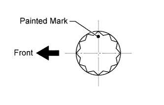
Check that the painted marks are positioned as shown in the illustration.
-
-
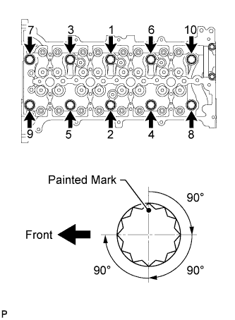
Step 3:
-
Retighten the cylinder head bolts by 90° in the sequence shown in the illustration.
-
Perform the above step twice.
-
Check that the painted marks are positioned as shown in the illustration.
-
-
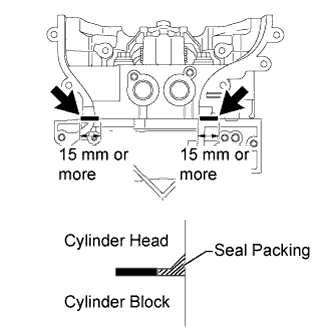
Apply seal packing between the cylinder head and cylinder block in the areas shown in the illustration.
Seal packing Toyota Genuine Seal Packing Black, Three Bond 1207B or equivalent Standard seal packing application length 15 mm (0.591 in.) or more Note
-
Before applying seal packing, clean the cylinder head and cylinder block surfaces near the head gasket. Be sure to remove any oil that has seeped in between the gasket and cylinder head or cylinder block.
-
When the contact surfaces are wet, wipe them off with an oil-free cloth before applying seal packing.
-
Wipe off any seal packing that seeps out from the groove in the cylinder head.
-
Do not start the engine for at least 4 hours after installation.
-
-
-
INSPECT VALVE LASH ADJUSTER ASSEMBLY
Note
-
Keep the lash adjuster free from dirt and foreign objects.
-
Use only clean engine oil.
-
Place the lash adjuster into a container full of new engine oil.
-
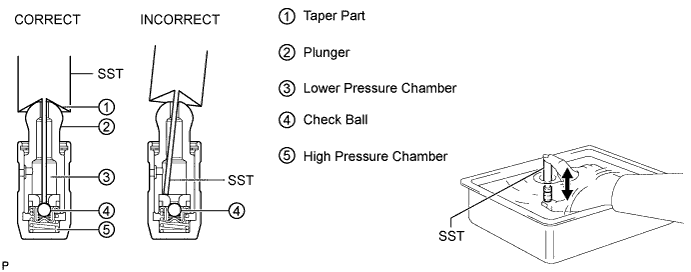
Insert SST tip into the lash adjuster plunger and use the tip to press down on the check ball inside the plunger.
- SST
- 09276-75010
-
Squeeze SST and the lash adjuster together to move the plunger up and down 5 to 6 times.
-
Check the movement of the plunger and bleed air.
OK Plunger moves up and down. Note
When bleeding high-pressure air from the compression chamber, make sure that the tip of SST is actually pressing the check ball as shown in the illustration. If the check ball is not pressed, air will not bleed.
-
After bleeding air, remove SST. Then quickly and firmly press the plunger repeatedly with your fingers.
OK Plunger can be pressed 3 times. If the plunger can still be compressed after pressing it 3 times, replace the lash adjuster with a new one.
-
-
INSTALL VALVE LASH ADJUSTER ASSEMBLY
-
Install the 16 valve lash adjusters.
Note
Install the lash adjusters to their original positions.
-
-
INSTALL NO. 1 VALVE ROCKER ARM SUB-ASSEMBLY
-
Install the 16 rocker arms to the lash adjusters.
-
-
INSTALL CAMSHAFT
-
Install the No. 2 bearing cap.
-
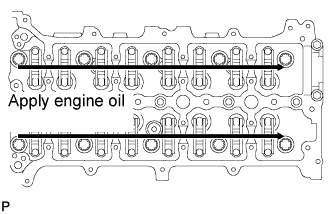
Apply clean engine oil to the cam of each camshaft, journals of the cylinder head and valve rocker arms.
-
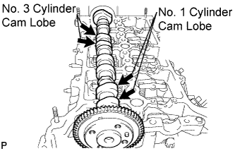
Place the No. 2 camshaft on the camshaft carrier as shown in the illustration so that the No. 1 and No. 3 cylinder cam lobes face upward.
Note
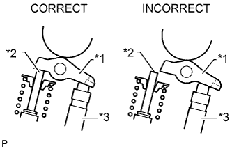
Before and after setting the camshaft and No. 2 camshaft on the engine, check that the rocker arm is firmly set to the lash adjuster.
Text in Illustration *1 Rocker Arm *2 Valve Stem *3 Lash Adjuster -
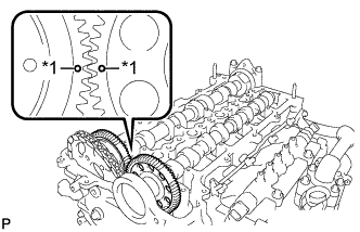
Text in Illustration *1 Dot Mark Align the camshaft and No. 2 camshaft timing mark (1 dot mark each).
-
Place the camshaft on the camshaft carrier.
-
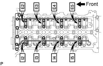
Set the camshaft bearing caps on the camshafts as shown in the illustration.
Tech Tips
Make sure of the marks and numbers on the camshaft bearing caps and place them in the proper position and direction.
-
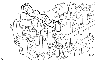
Set the oil delivery pipes on the camshaft bearing caps.
-
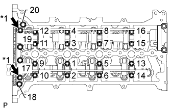
Text in Illustration *1 Union Bolt Temporarily install the 2 union bolts and 20 bolts.
-
Uniformly tighten the bolts in several steps, in the sequence shown in the illustration.
- Torque:
- for 1 to 16
- 10 N*m { 102 kgf*cm, 7 ft.*lbf }
- for 17 to 20
- 21 N*m { 214 kgf*cm, 15 ft.*lbf }
-
Tighten the 2 union bolts.
- Torque:
- 17 N*m { 173 kgf*cm, 13 ft.*lbf }
-
-
INSTALL CRANKSHAFT PULLEY SET CRANKSHAFT KEY
-
Install the 2 keys to the crankshaft.
-
-
INSTALL CAMSHAFT TIMING SPROCKET
-
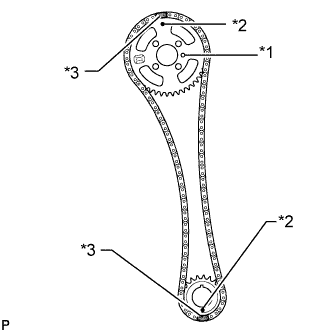
Text in Illustration *1 Straight Pin *2 Timing Mark *3 Yellow Paint Mark Install the crankshaft timing sprocket and camshaft timing sprocket to the chain so that the timing marks of the sprockets and paint marks of the chain are aligned.
-
Install the camshaft timing sprocket to the No. 2 camshaft by fitting the straight pin of the No. 2 camshaft into the hole on the camshaft timing sprocket.
-
Install the crankshaft timing sprocket to the crankshaft.
-
While holding the hexagon portion of the No. 2 camshaft, install and uniformly tighten the 4 bolts of the No. 2 camshaft.
- Torque:
- 20 N*m { 204 kgf*cm, 15 ft.*lbf }
-
-
INSTALL OIL PUMP DRIVE GEAR
-
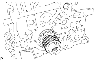
Install the oil pump drive gear to the crankshaft.
-
-
INSTALL NO. 1 CHAIN VIBRATION DAMPER
-
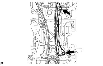
Install the No. 1 chain vibration damper with the 2 bolts.
- Torque:
- 21 N*m { 214 kgf*cm, 15 ft.*lbf }
-
-
INSTALL CHAIN TENSIONER SLIPPER
-
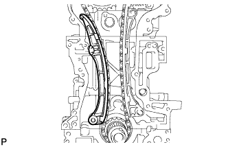
Install the chain tensioner slipper.
-
-
INSTALL NO. 1 CHAIN TENSIONER ASSEMBLY
-
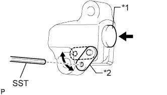
Text in Illustration *1 Plunger *2 Stopper Plate Move the stopper plate upward to release the lock, and push the plunger deep into the tensioner.
-
Move the stopper plate downward to set the lock, and insert SST into the stopper plate hole.
- SST
- 09240-00020 ( 09242-00200 )
-
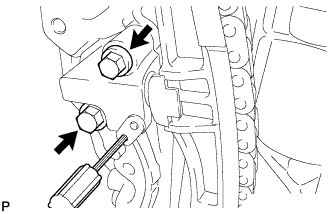
Install the chain tensioner with the 2 bolts.
- Torque:
- 9.0 N*m { 92 kgf*cm, 80 in.*lbf }
-
Remove SST.
-
-
INSTALL FRONT CRANKSHAFT OIL SEAL
-
Text in Illustration *1 Oil Seal *2 Timing Chain Cover Using SST and a hammer, tap in a new oil seal until its surface is flush with the timing chain cover edge.
- SST
- 09223-50010
Standard depth 0 to 0.6 mm (0 to 0.236 in.) Note
-
Keep the lip of the oil seal free from foreign matter.
-
Do not tap in the oil seal at an angle.
-
Apply MP grease to the lip of the oil seal.
Note
-
Do not allow foreign matter to contact the lip of the oil seal.
-
Do not allow MP grease to contact the dust seal.
-
-
-
INSTALL TIMING CHAIN COVER SUB-ASSEMBLY
-
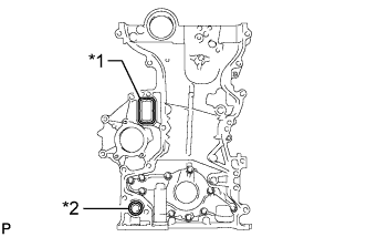
Text in Illustration *1 Gasket *2 O-Ring Install a new gasket and new O-ring to the timing chain cover.
-
Remove any old seal packing material.
-
Apply seal packing in a continuous line to the timing chain cover as shown in the following illustration.
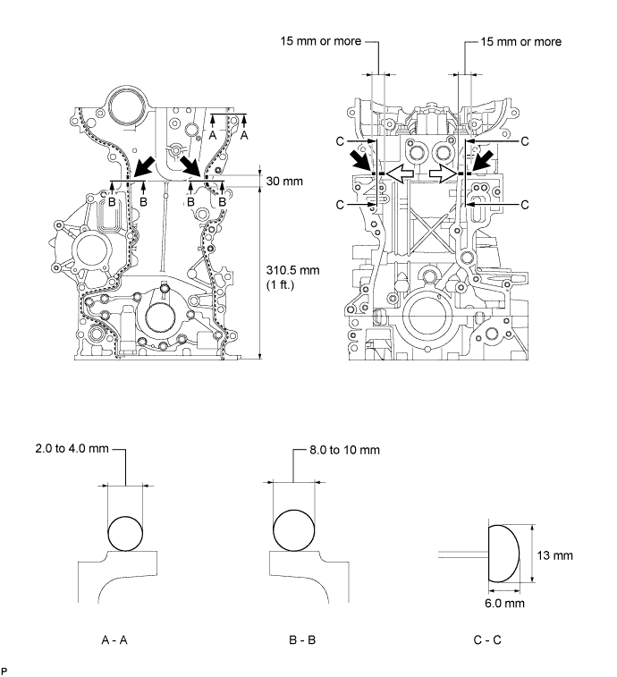
Seal packing Toyota Genuine Seal Packing Black, Three Bond 1207B or equivalent Apply Seal Packing as Follows Area Seal Packing Diameter (Round) Seal Packing Dimension (Flat) Seal Packing Application Length A - A 2.0 to 4.0 mm (0.0787 to 0.157 in.) - - B - B 8.0 to 10 mm (0.315 to 0.394 in.) - 30 mm (1.18 in.) C - C - 13 mm (0.512 in.) or more wide and 6.0 mm (0.236 in.) or more thick 15 mm (0.591 in.) Note
-
Be sure to clean and degrease the contact surfaces, especially the 4 areas indicated by the arrows in the illustration.
-
When the contact surfaces are wet, wipe them off with an oil-free cloth before applying seal packing.
-
When applying seal packing to area C - C, apply it in the direction of the white arrows in the illustration.
-
Install the timing chain cover within 3 minutes and tighten the bolts within 15 minutes after applying seal packing.
-
Do not start the engine for at least 4 hours after installation.
-
-
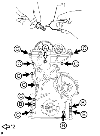
Text in Illustration *1 Adhesive *2 Bolt and New Seal Washer Apply adhesive to the 4 bolts labeled B.
Adhesive Toyota Genuine Adhesive 1324, Three Bond 1324 or equivalent -
Temporarily install the timing chain cover and a new seal washer with the 13 bolts.
Bolt Length Item Specified Condition Bolt A 60 mm (2.36 in.) Bolt B 30 mm (1.18 in.) Bolt C 30 mm (1.18 in.) Tech Tips
Bolt B and C are identical.
-
Tighten the 12 bolts labeled B and C.
- Torque:
- 23 N*m { 229 kgf*cm, 17 ft.*lbf }
-
Tighten the bolt labeled A.
- Torque:
- 21 N*m { 214 kgf*cm, 15 ft.*lbf }
-
-
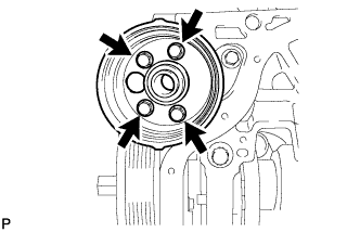
INSTALL CRANKSHAFT PULLEY
-
Align the keyway of the pulley with the key located on the crankshaft, then slide the pulley into place to install it.
-
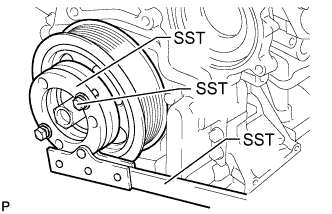
Using SST, install the pulley bolt.
- SST
- 09213-58014 ( 91551-80840 )
- 09330-00021
- Torque:
- 300 N*m { 3059 kgf*cm, 221 ft.*lbf }
-
-
INSTALL OIL STRAINER SUB-ASSEMBLY
-
Install a new O-ring to the oil strainer.
-
Apply a light coat of engine oil to the O-ring.
-
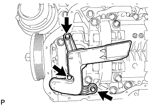
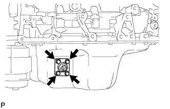
Install the oil strainer with the 3 bolts.
- Torque:
- 9.0 N*m { 92 kgf*cm, 80 in.*lbf }
-
-
INSTALL OIL FILTER BRACKET
-
Install a new gasket to the oil filter bracket.
-
Install the oil filter bracket with the 4 bolts.
- Torque:
- 9.0 N*m { 92 kgf*cm, 80 in.*lbf }
-
-
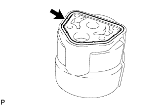
INSTALL OIL FILTER ELEMENT
-
Clean the inside of the oil filter cap, its threads and its O-ring groove.
-
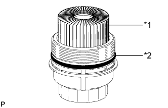
Text in Illustration *1 New Oil Filter Element *2 New O-Ring Apply a small amount of engine oil to a new O-ring and install it to the oil filter cap.
-
Set a new oil filter element in the oil filter cap.
-
Remove any dirt or foreign matter from the installation surface of the engine.
-
Apply a small amount of engine oil to the O-ring again and temporarily install the oil filter cap.
-
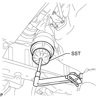
Using SST, tighten the oil filter cap.
- SST
- 09228-06501
- Torque:
- 40 N*m { 408 kgf*cm, 30 ft.*lbf }
-
-
INSTALL NO. 2 OIL PAN SUB-ASSEMBLY
-
Remove any old seal packing material.
-
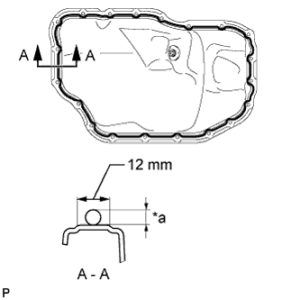
Apply seal packing in a continuous line as shown in the illustration.
Seal packing Toyota Genuine Seal Packing Black, Three Bond 1207B or equivalent Standard Seal Packing Dimension Area Seal Packing Diameter Seal Packing Application Length A - A 4.0 to 7.0 mm (0.157 to 0.276 in.) 12 mm (0.472 in.) Note
-
Remove any oil from the contact surface.
-
Install the oil pan within 3 minutes and tighten the bolts within 10 minutes after applying seal packing.
-
Do not start the engine for at least 4 hours after installing.
-
-
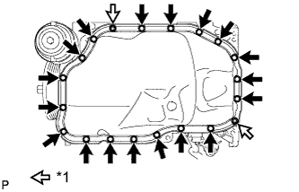
Text in Illustration *1 Nut Install the oil pan with the 18 bolts and 2 nuts.
- Torque:
- 11 N*m { 107 kgf*cm, 8 ft.*lbf }
-
-
INSTALL CYLINDER HEAD COVER SUB-ASSEMBLY
-
Clean the contact surface of the cylinder head cover, cylinder head and timing chain cover.
-
Install a new cylinder head cover gasket and No. 2 gasket to the gasket groove on the cylinder head cover.
-
Text in Illustration *1 Seal Packing Apply seal packing to the contact surface between the cylinder head and cylinder head cover as shown in the illustration.
Seal packing Toyota Genuine Seal Packing Black, Three Bond 1207B or equivalent Standard seal diameter 8 mm (0.315 in.) Note
-
Remove any oil from the contact surface.
-
Install the cylinder head cover within 3 minutes after applying seal packing.
-
Do not apply engine oil for at least 2 hours after installing.
-
-
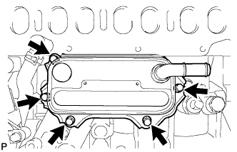
Text in Illustration *1 Nut Install the cylinder head cover with the 14 bolts, 4 nozzle holder clamp seats and nut.
Uniformly tighten the bolts and nut in several passes.
- Torque:
- for bolt A (Nozzle holder clamp seat)
- 16 N*m { 167 kgf*cm, 12 ft.*lbf }
- for other bolts, nut
- 11 N*m { 112 kgf*cm, 8 ft.*lbf }
-
-
INSTALL OIL FILLER CAP SUB-ASSEMBLY
-
INSTALL WATER INLET HOUSING
-
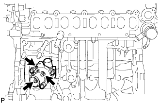
Install a new gasket and the water inlet housing with the 3 nuts.
- Torque:
- 9.0 N*m { 92 kgf*cm, 80 in.*lbf }
-
-
INSTALL ENGINE OIL LEVEL SENSOR
-
Install the sensor with the 4 bolts.
- Torque:
- 7.0 N*m { 71 kgf*cm, 62 in.*lbf }
-
-
INSTALL NO. 1 OIL COOLER BRACKET
-
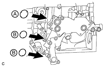
Apply engine oil to the 2 new O-rings labeled B in the illustration.
Note
Do not apply engine oil to the new O-ring labeled A in the illustration.
-
Install 3 new O-rings to the oil cooler bracket.
-
Text in Illustration *1 Nut Install the No. 1 oil cooler bracket with the 6 bolts and nut.
- Torque:
- 11 N*m { 112 kgf*cm, 8 ft.*lbf }
-
-
INSTALL OIL COOLER ASSEMBLY
-
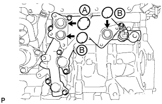
Apply engine oil to the 2 new O-rings labeled B in the illustration.
Note
Do not apply engine oil to the new O-ring labeled A in the illustration.
-
Install 3 new O-rings to the oil cooler bracket.
-
Install the oil cooler with the 5 bolts.
- Torque:
- 11 N*m { 112 kgf*cm, 8 ft.*lbf }
-
-
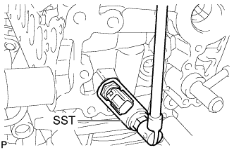
INSTALL ENGINE OIL PRESSURE SWITCH ASSEMBLY
-
Remove the adhesive from the threads of the oil pressure switch and the bolt hole of the oil filter bracket.
-
Text in Illustration *1 Adhesive Apply adhesive to 2 or 3 threads of the oil pressure switch.
Adhesive Toyota Genuine Adhesive 1344, Three Bond 1344 or equivalent Note
Do not apply adhesive to the oil inlet port of the sensor.
-
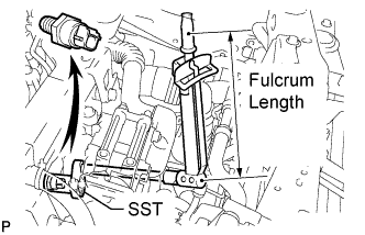
Using SST, install the engine oil pressure switch.
- SST
- 09224-00010
- Torque:
- without SST
- 13 N*m { 133 kgf*cm, 10 ft.*lbf }
- with SST
- 12 N*m { 122 kgf*cm, 9 ft.*lbf }
Tech Tips
-
Use a torque wrench with a fulcrum length of 300 mm (11.8 in.).
-
Make sure SST and the wrench are connected in a straight line.
Note
Do not start the engine for at least 1 hour after installation.
-
Connect the engine oil pressure switch connector.
-
-
INSTALL WATER PUMP ASSEMBLY
-
Install a new gasket to the timing chain cover.
-
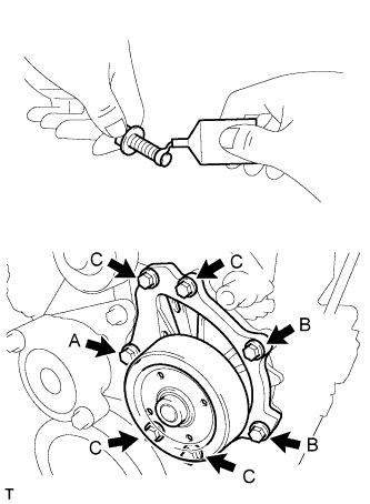
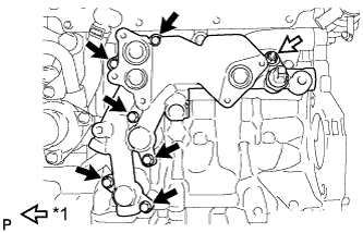
Apply adhesive to 2 or 3 threads of the bolt labeled A as shown in the illustration.
Adhesive Toyota Genuine Adhesive 1324, Three Bond 1324 or equivalent Standard Bolt Length Item Specified Condition Bolt A and C 45 mm (1.77 in.) Bolt B 30 mm (1.18 in.) -
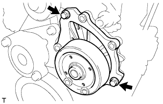
Install the water pump with the 2 bolts shown in the illustration.
- Torque:
- 23 N*m { 229 kgf*cm, 17 ft.*lbf }
-
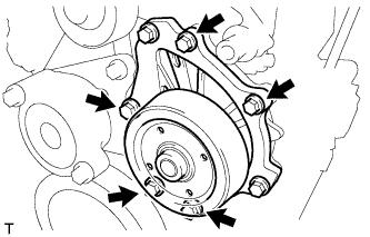
Install the 5 bolts shown in the illustration.
- Torque:
- 23 N*m { 229 kgf*cm, 17 ft.*lbf }
-
-
INSTALL ENGINE COOLANT TEMPERATURE SENSOR
-
Install a new gasket to the sensor.
-
Using SST, install the sensor.
- SST
- 09817-33190
- Torque:
- 20 N*m { 204 kgf*cm, 15 ft.*lbf }
-
-
INSTALL CRANKSHAFT POSITION SENSOR
-
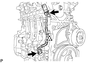
Install the sensor with the 2 bolts.
- Torque:
- 8.8 N*m { 90 kgf*cm, 78 in.*lbf }
-
Connect the sensor harness and install the clip.
-
-
INSTALL CAMSHAFT POSITION SENSOR
-
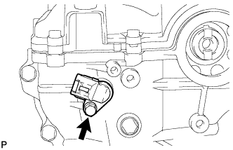
Install the sensor with the bolt.
- Torque:
- 8.8 N*m { 90 kgf*cm, 78 in.*lbf }
-
-
INSTALL INJECTOR ASSEMBLY
Note
Before installing the injector, check for carbon, foreign matter, etc. on the seal surfaces of the cylinder head and injector. If there is foreign matter, remove it before installing the injector.
-
Install 4 new nozzle seats to the cylinder head.
-
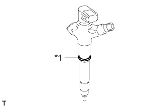
Text in Illustration *1 New O-Ring Install a new O-ring to each injector.
-
Apply a light coat of engine oil to the O-rings on each injector.
-
Install the 4 injectors to the cylinder head.
Note
Fit the injectors to the nozzle seats.
-
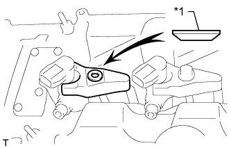
Text in Illustration *1 Washer Install the nozzle holder clamps and washers as shown in the illustration.
Note
Pay attention to the mounting orientation (beveled edge) of the washer.
-
Temporarily install the nozzle holder clamp bolts.
Note
When temporarily attaching the nozzle holder clamp and the nozzle holder clamp bolt, be careful not to position them at an angle.
Tech Tips
Apply a light coat of engine oil on the threads of the nozzle holder clamp bolts.
-
Temporarily install the 4 injection pipes.
-
Temporarily install the No. 1 leakage pipe with 4 new gaskets, the 4 union bolts and bolt.
-
Tighten the 4 nozzle holder clamp bolts.
- Torque:
- 25 N*m { 255 kgf*cm, 18 ft.*lbf }
-
-
INSTALL NO. 1 NOZZLE LEAKAGE PIPE
-
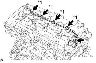
Text in Illustration *1 Union Bolt Install 4 new gaskets and the No. 1 nozzle leakage pipe with the 4 union bolts and bolt.
- Torque:
- for union bolt
- 18 N*m { 184 kgf*cm, 13 ft.*lbf }
- for bolt
- 21 N*m { 209 kgf*cm, 15 ft.*lbf }
-
-
INSTALL NO. 2 NOZZLE LEAKAGE PIPE
-
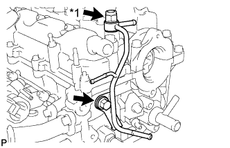
Text in Illustration *1 Check Valve Temporarily install the No. 2 nozzle leakage pipe and a new gasket with the check valve and bolt.
-
Tighten the check valve.
- Torque:
- 32 N*m { 321 kgf*cm, 23 ft.*lbf }
-
Tighten the bolt.
- Torque:
- 32 N*m { 321 kgf*cm, 23 ft.*lbf }
-