ENGINE UNIT INSTALLATION

Note
-
When replacing the injectors (including shuffling the injectors between the cylinders), common rail, intake manifold or cylinder head, it is necessary to replace the injection pipes with new ones.
-
When replacing the fuel supply pump, common rail, intake manifold or cylinder head, it is necessary to replace the fuel inlet pipe with a new one.
-
INSTALL DRIVE SHAFT BEARING BRACKET
-
Install the bearing bracket with the 3 bolts.
- Torque:
- 64 N*m { 653 kgf*cm, 47 ft.*lbf }
-
-
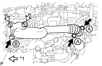
INSTALL EXHAUST MANIFOLD WITH TURBOCHARGER SUB-ASSEMBLY
-
Text in Illustration *1 Collar *2 Groove Temporarily install a new gasket, and the exhaust manifold and 2 collars with the 2 nuts labeled A. Tighten the nuts until the mating surface of the exhaust manifold contacts the cylinder head.
-
Temporarily install the 6 collars with the 6 nuts.
Tech Tips
-
When installing the collars, pay attention to the mounting orientation. The ring groove of the collar should be on the outside. Refer to the illustration.
-
Do not fully tighten the nuts as doing so may result in misalignment of the exhaust manifold.
-
-
Install a new gasket and the turbocharger with 3 new nuts.
- Torque:
- 60 N*m { 612 kgf*cm, 44 ft.*lbf }
-
Connect the vacuum hose.
-
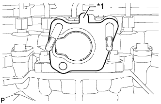
Text in Illustration *1 New Turbocharger Stay *2 Collar Install the 2 collars and a new turbocharger stay with the 2 nuts.
- Torque:
- 36 N*m { 367 kgf*cm, 27 ft.*lbf }
Note
Do not reuse the turbocharger stay.
-
Tighten the 8 nuts of the exhaust manifold.
- Torque:
- 47 N*m { 479 kgf*cm, 35 ft.*lbf }
-
-
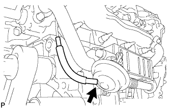
INSTALL NO. 2 TURBO OIL PIPE
-
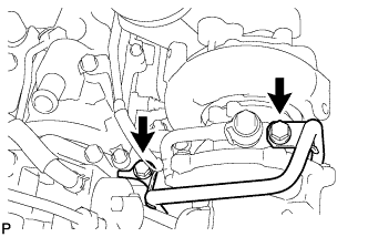
Install the No. 2 turbo oil pipe and 2 new gaskets with the 2 union bolts.
- Torque:
- 35 N*m { 357 kgf*cm, 26 ft.*lbf }
-
Connect the vacuum hose.
-
-
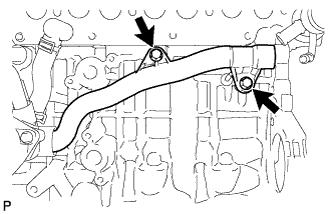
INSTALL NO. 5 WATER BY-PASS PIPE (for Automatic Transaxle)
-
Install the No. 5 water by-pass pipe with the 2 bolts.
- Torque:
- 28 N*m { 286 kgf*cm, 21 ft.*lbf }
-
-
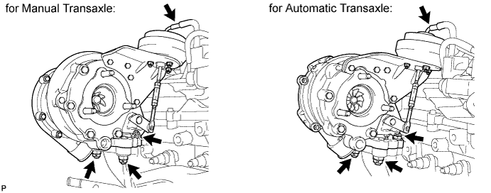
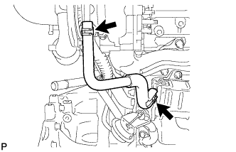
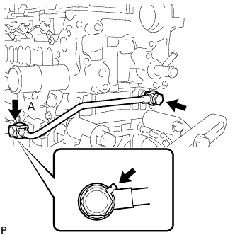
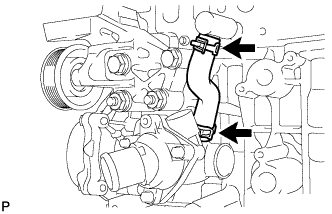
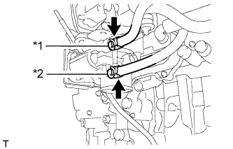
INSTALL NO. 2 TURBO WATER PIPE SUB-ASSEMBLY (for Manual Transaxle)
-
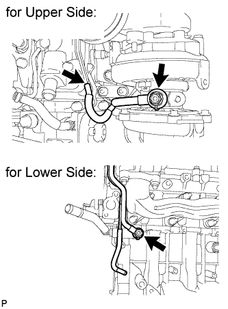
Text in Illustration *1 Union Bolt Install the No. 2 turbo water pipe and a new gasket with the union bolt and bolt.
- Torque:
- for bolt
- 28 N*m { 286 kgf*cm, 21 ft.*lbf }
- for union bolt
- 38 N*m { 387 kgf*cm, 28 ft.*lbf }
-
-
CONNECT NO. 3 WATER BY-PASS HOSE
-
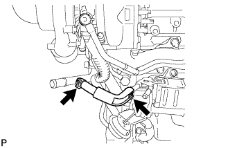
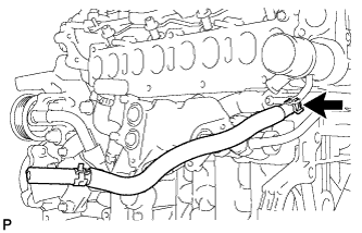
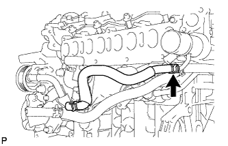
INSTALL NO. 1 TURBO WATER PIPE SUB-ASSEMBLY (for Manual Transaxle)
-
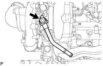
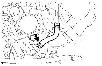
Install the No. 1 turbo water pipe and a new gasket with the union bolt.
- Torque:
- 38 N*m { 387 kgf*cm, 28 ft.*lbf }
Note
Make sure there is no coolant on the union bolt.
-
-
INSTALL NO. 1 TURBO INSULATOR
-
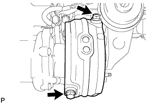
Install the No. 1 turbo insulator with the 2 bolts.
- Torque:
- 21 N*m { 209 kgf*cm, 15 ft.*lbf }
-
-
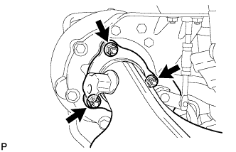
INSTALL TURBO OIL OUTLET PIPE
-
Install 2 new gaskets to the turbo oil outlet pipe.
-
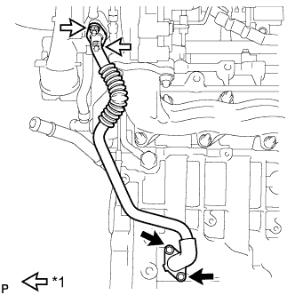
Text in Illustration *1 Nut Install the turbo oil outlet pipe with the 2 bolts and 2 nuts.
- Torque:
- 11 N*m { 112 kgf*cm, 8 ft.*lbf }
-
-
INSTALL EGR COOLER WITH PIPE ASSEMBLY
-
Install a new O-ring to the EGR cooler with pipe.
-
Install a new gasket to the EGR cooler and a new gasket to the No. 1 EGR pipe.
-
Temporarily install the EGR cooler with pipe with the 6 bolts and 2 nuts labeled A, B and C.
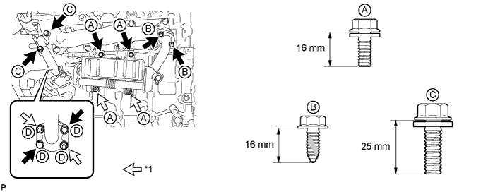
Text in Illustration *1 Nut Bolt Length Item Specified Condition Bolt A 16 mm (0.630 in.) Bolt B 16 mm (0.630 in.) Bolt C 25 mm (0.984 in.) -
Tighten the 2 bolts and 2 nuts labeled A shown in the illustration.
- Torque:
- 10 N*m { 102 kgf*cm, 7 ft.*lbf }
-
Tighten the 2 bolts labeled B shown in the illustration.
- Torque:
- 16 N*m { 163 kgf*cm, 12 ft.*lbf }
-
Tighten the 2 bolts labeled C shown in the illustration.
- Torque:
- 24 N*m { 245 kgf*cm, 18 ft.*lbf }
-
Tighten the 2 bolts and 2 nuts labeled D shown in the illustration.
- Torque:
- 21 N*m { 214 kgf*cm, 15 ft.*lbf }
-
Connect the vacuum hose.
-
-
INSTALL NO. 2 WATER BY-PASS HOSE (for Automatic Transaxle)
-
INSTALL NO. 5 WATER BY-PASS HOSE (for Manual Transaxle)
-
INSTALL NO. 1 TURBO WATER HOSE (for Manual Transaxle)
-
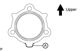
INSTALL EXHAUST MANIFOLD CONVERTER SUB-ASSEMBLY
-
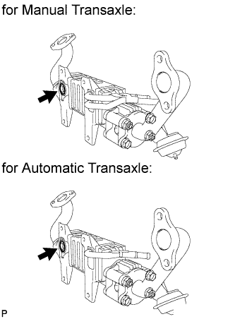
Install a new gasket to the turbocharger.
Tech Tips
Make sure that the part labeled A is facing downwards as shown in the illustration.
-
Temporarily install the exhaust manifold converter with the 3 nuts.
-
Temporarily install the No. 2 exhaust manifold stay with the 2 bolts and nut.
-
Temporarily install the No. 2 manifold stay with the 3 bolts.
-
Temporarily install the manifold stay with the bolt and nut.
-
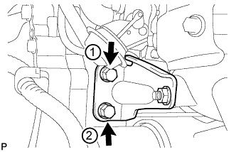
Tighten the 2 bolts of the No. 2 exhaust manifold stay in the order shown in the illustration.
- Torque:
- 56 N*m { 571 kgf*cm, 41 ft.*lbf }
-
Tighten the 3 nuts of the exhaust manifold converter.
- Torque:
- 25 N*m { 255 kgf*cm, 18 ft.*lbf }
Note
Tighten the nuts while pressing the exhaust manifold converter against the engine.
-
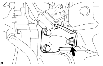
Tighten the nut of the No. 2 exhaust manifold stay.
- Torque:
- 56 N*m { 571 kgf*cm, 41 ft.*lbf }
-
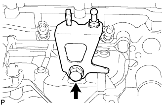
Tighten the bolt of the No. 2 manifold stay shown in the illustration.
- Torque:
- 56 N*m { 571 kgf*cm, 41 ft.*lbf }
Note
Tighten the bolt while pressing the No. 2 manifold stay against the exhaust manifold converter and cylinder block.
-
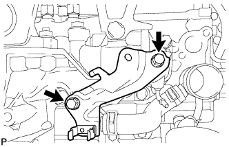
Tighten the 2 bolts of the No. 2 manifold stay shown in the illustration.
- Torque:
- 56 N*m { 571 kgf*cm, 41 ft.*lbf }
-
Tighten the bolt of the manifold stay.
- Torque:
- 25 N*m { 255 kgf*cm, 18 ft.*lbf }
Note
Tighten the bolt while pressing the manifold stay against the exhaust manifold converter and cylinder block.
-
Tighten the nut of the manifold stay.
- Torque:
- 25 N*m { 255 kgf*cm, 18 ft.*lbf }
-
Connect the 2 connectors.
-
-
INSTALL NO. 1 MANIFOLD CONVERTER INSULATOR
-
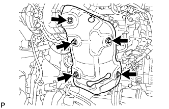
Install the No. 1 manifold converter insulator with the 5 bolts.
- Torque:
- 29 N*m { 291 kgf*cm, 21 ft.*lbf }
-
-
INSTALL VACUUM SWITCHING VALVE BRACKET
-
Install the vacuum switching valve bracket with the 5 bolts.
- Torque:
- 9.0 N*m { 92 kgf*cm, 80 in.*lbf }
-
Connect the 2 vacuum hoses.
-
-
INSTALL NO. 1 VACUUM TRANSMITTING PIPE SUB-ASSEMBLY
-
Install the No. 1 vacuum transmitting pipe with the bolt.
- Torque:
- 9.0 N*m { 92 kgf*cm, 80 in.*lbf }
-
Connect the 2 vacuum hoses.
-
-
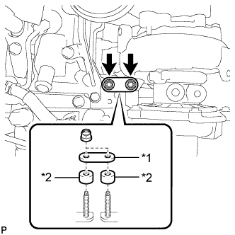
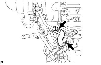
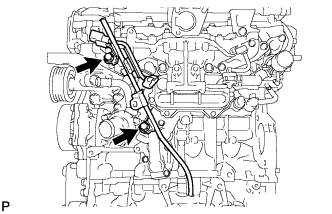
INSTALL NO. 1 TURBO OIL PIPE
-
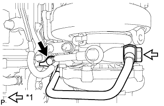
Install the oil pipe and 2 new gaskets with the 2 union bolts.
- Torque:
- 35 N*m { 357 kgf*cm, 26 ft.*lbf }
Tech Tips
Be sure to install union bolt A so that the gasket is positioned as shown in the illustration.
-
-
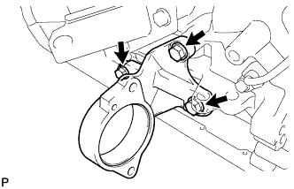
INSTALL NO. 3 WATER BY-PASS PIPE
-
Apply soapy water to a new O-ring and install it to the by-pass pipe.
-
Install the by-pass pipe with the 2 bolts.
- Torque:
- 21 N*m { 214 kgf*cm, 15 ft.*lbf }
-
-
INSTALL FUEL HOSE PROTECTOR
-
Install the fuel hose protector to the cylinder head.
- Torque:
- 21 N*m { 214 kgf*cm, 15 ft.*lbf }
-
-
INSTALL SUPPLY PUMP ASSEMBLY
-
Install a new O-ring to the supply pump.
-
Install the supply pump drive coupling.
Tech Tips
Line up the coupling with the groove in the camshaft end.
Note
When reusing the coupling, it must be installed in the same orientation (top/bottom, front/back) as when it was removed,
-
Install the supply pump with the 2 bolts.
- Torque:
- 21 N*m { 209 kgf*cm, 15 ft.*lbf }
Tech Tips
Line up the end of the supply pump drive shaft with the supply pump drive coupling.
Note
Apply engine oil to the O-ring of the supply pump.
-
-
INSTALL NO. 3 FUEL HOSE
-
INSTALL FUEL INJECTOR SEAL
-
Text in Illustration *1 Fuel Injector Seal Install a new fuel injector seal to the exhaust fuel addition injector.
-
-
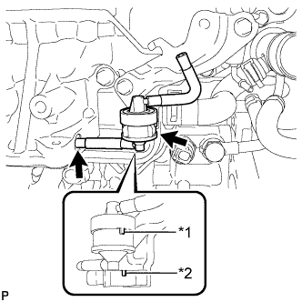
INSTALL EXHAUST FUEL ADDITION INJECTOR ASSEMBLY
Note
If there is foreign matter on the installation surface of the exhaust fuel addition injector, be sure to clean it before installation.
-
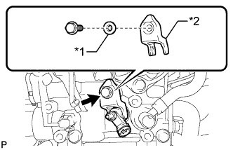
Install a new gasket, the exhaust fuel addition injector, nozzle holder clamp and washer with the bolt.
- Torque:
- 29 N*m { 296 kgf*cm, 21 ft.*lbf }
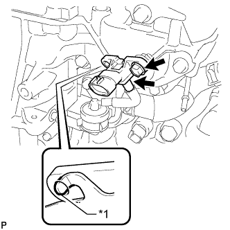
Text in Illustration *1 Washer *2 Nozzle Holder Clamp Tech Tips
Align the nozzle holder clamp with the cutouts of the injector as shown in the illustration.
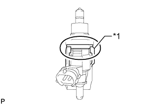
Text in Illustration *1 Nozzle Holder Clamp
-
-
INSTALL FUEL TUBE SUB-ASSEMBLY
-

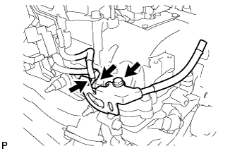
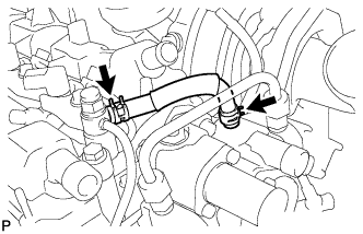
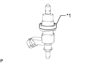
Text in Illustration *1 Check Valve Temporarily install the fuel tube and 2 new gaskets with the check valve and union bolt.
-
Tighten the check valve.
- Torque:
- 32 N*m { 321 kgf*cm, 23 ft.*lbf }
-
Tighten the union bolt.
- Torque:
- 23 N*m { 235 kgf*cm, 17 ft.*lbf }
-
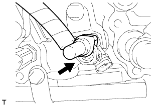
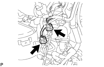
Connect the fuel tube connector to the injector.
-
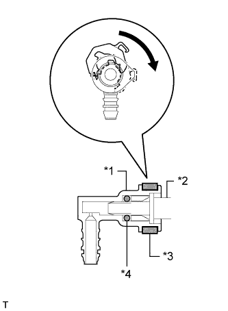
Text in Illustration *1 Fuel Tube Connector *2 Injector *3 Retainer *4 O-Ring Turn the retainer in the direction indicated by the arrow until it makes a "click" sound.
Note
If the fuel tube connector is not inserted to the correct position on the injector, the retainer cannot be turned far enough in the direction of the arrow.
-
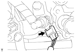
Connect the exhaust fuel addition injector connector.
-
-
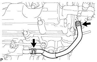
INSTALL FUEL HOSE PROTECTOR
-
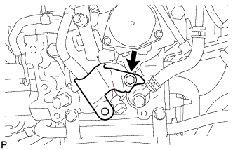
Install the fuel hose protector with the bolt.
- Torque:
- 21 N*m { 209 kgf*cm, 15 ft.*lbf }
-
-
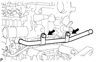
INSTALL NO. 2 WATER BY-PASS PIPE
-
Install the No. 2 water by-pass pipe with the 2 bolts.
- Torque:
- 11 N*m { 112 kgf*cm, 8 ft.*lbf }
-
-
INSTALL NO. 4 WATER BY-PASS HOSE
-
INSTALL NO. 8 WATER BY-PASS HOSE
-
INSTALL NO. 6 WATER BY-PASS HOSE
-
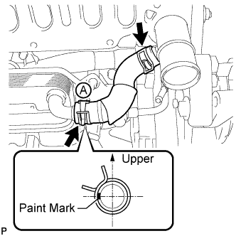
INSTALL WATER BY-PASS HOSE
Tech Tips
Make sure the claws of hose clamp A are positioned above the paint mark as shown in the illustration.
-
INSTALL NO. 1 CYLINDER BLOCK INSULATOR
-
Install the No. 1 cylinder block insulator to the cylinder block.
Note
Be sure to install the oil cooler before installing the No. 1 cylinder block insulator.
-
-
INSTALL GLOW PLUG ASSEMBLY
-
Using a 10 mm deep socket wrench, install the 4 glow plugs.
- Torque:
- 12 N*m { 125 kgf*cm, 9 ft.*lbf }
-
Install the glow plug connector with the 4 nuts.
- Torque:
- 2.2 N*m { 22 kgf*cm, 19 in.*lbf }
-
Install the 4 grommets.
-
-
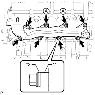
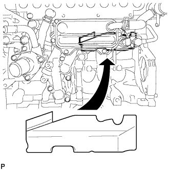
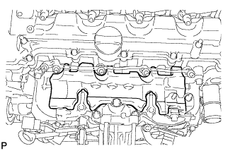
INSTALL INTAKE MANIFOLD
-
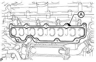
Install a new gasket to the cylinder head.
Tech Tips
Install the gasket with the part labeled A facing the right side of the vehicle as shown in the illustration.
-
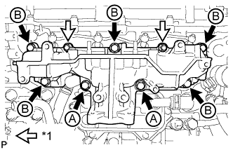
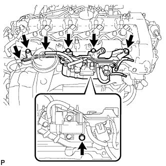
Text in Illustration *1 Nut Install the intake manifold with the 7 bolts and 2 nuts.
- Torque:
- 23 N*m { 235 kgf*cm, 17 ft.*lbf }
Bolt Length Item Specified Condition Bolt A 90 mm (3.54 in.) Bolt B 25 mm (0.984 in.)
-
-
INSTALL NO. 2 INTAKE MANIFOLD
-
Install a new gasket and the No. 2 intake manifold with the bolt and 2 nuts.
- Torque:
- 24 N*m { 245 kgf*cm, 18 ft.*lbf }
-
-
INSTALL ENGINE COVER BRACKET
-
Install the engine cover bracket with the bolt.
- Torque:
- 20 N*m { 204 kgf*cm, 15 ft.*lbf }
-
-
INSTALL GAS FILTER BRACKET
-
Install the gas filter bracket with the 2 bolts.
- Torque:
- 8.8 N*m { 90 kgf*cm, 78 in.*lbf }
-
-
INSTALL NO. 1 GAS FILTER
-
Text in Illustration *1 Protrusion *2 Groove Install the No. 1 gas filter to the gas filter bracket.
Note
Make sure the protrusion of the No. 1 gas filter is aligned with the groove of the gas filter bracket.
-
Connect the vacuum hose.
-
-
INSTALL DIESEL TURBO PRESSURE SENSOR
-
Text in Illustration *1 Protrusion Install the sensor with the bolt.
- Torque:
- 8.8 N*m { 90 kgf*cm, 78 in.*lbf }
Note
Make sure the protrusion of the gas filter bracket is inserted into the hole of the sensor.
-
Connect the vacuum hose.
-
-
INSTALL INTAKE MANIFOLD INSULATOR
-
Install the intake manifold insulator to the intake manifold.
-
-
INSTALL COMMON RAIL ASSEMBLY
-
Install the common rail with the 2 bolts.
- Torque:
- 21 N*m { 209 kgf*cm, 15 ft.*lbf }
-
-
INSTALL NO. 4 FUEL HOSE
-
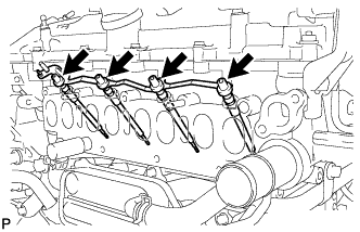
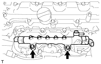
INSTALL INJECTION PIPE
-
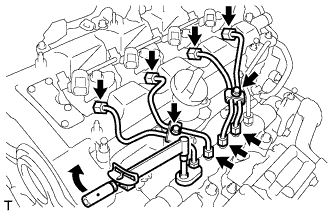
Using a 14 mm union nut wrench, tighten the 4 nuts at the common rail end of the injection pipes.
- Torque:
- 30 N*m { 306 kgf*cm, 22 ft.*lbf }
Note
Use the formula to calculate special torque values for situations where a union nut wrench is combined with a torque wrench Click here.
-
Using a 14 mm union nut wrench, tighten the 4 nuts at the injector end of the injection pipes.
- Torque:
- 30 N*m { 306 kgf*cm, 22 ft.*lbf }
Note
Use the formula to calculate special torque values for situations where a union nut wrench is combined with a torque wrench Click here.
-
Install the 4 injection pipe clamps with the 2 bolts.
- Torque:
- 5.0 N*m { 51 kgf*cm, 44 in.*lbf }
-
-
INSTALL FUEL INLET PIPE SUB-ASSEMBLY
-
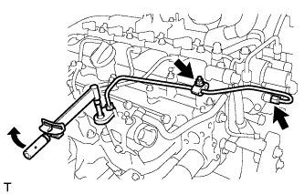
Temporarily install the fuel inlet pipe with the 2 clamps and nut.
-
Using a 14 mm union nut wrench, first tighten the nut at the common rail end of the fuel inlet pipe.
- Torque:
- 30 N*m { 306 kgf*cm, 22 ft.*lbf }
Note
Use the formula to calculate special torque values for situations where a union nut wrench is combined with a torque wrench Click here.
-
Using a 14 mm union nut wrench, tighten the nut at the supply pump end of the fuel inlet pipe.
- Torque:
- 30 N*m { 306 kgf*cm, 22 ft.*lbf }
Note
Use the formula to calculate special torque values for situations where a union nut wrench is combined with a torque wrench Click here.
-
Tighten the No. 2 injection pipe clamp nut.
- Torque:
- 5.0 N*m { 51 kgf*cm, 44 in.*lbf }
-
-
INSTALL ENGINE OIL LEVEL DIPSTICK GUIDE
-
Install a new O-ring to the engine oil level dipstick guide.
-
Install the engine oil level dipstick guide with the 2 bolts.
- Torque:
- 33 N*m { 337 kgf*cm, 24 ft.*lbf }
-
Install the engine oil level dipstick.
-
-
INSTALL ELECTRIC EGR CONTROL VALVE ASSEMBLY
-
Text in Illustration *1 Protrusion Install a new gasket.
Note
Make sure the protrusion of the gasket is facing upward as shown in the illustration.
-
Install the electric EGR control valve.
-
-
INSTALL NO. 2 EGR PIPE SUB-ASSEMBLY
-
Install a new gasket to the electric EGR control valve.
-
Install a new gasket to the No. 2 EGR pipe.
-
Text in Illustration *1 Nut Temporarily install the No. 2 EGR pipe with the 3 bolts and 2 nuts.
Bolt Length Item Specified Condition Bolt A 25 mm (0.984 in.) Bolt B 70 mm (2.76 in.) -
Tighten the 2 bolts labeled A shown in the illustration.
- Torque:
- 24 N*m { 245 kgf*cm, 18 ft.*lbf }
-
Tighten the bolt labeled B and 2 nuts shown in the illustration.
- Torque:
- 24 N*m { 245 kgf*cm, 18 ft.*lbf }
-
Connect the electric EGR control valve connector.
-
-
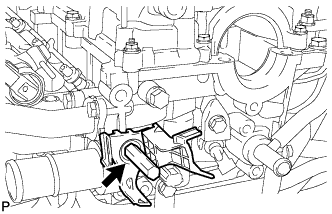
INSTALL EGR VALVE BRACKET
-
Install the 2 EGR valve brackets with the 3 bolts.
- Torque:
- 24 N*m { 245 kgf*cm, 18 ft.*lbf }
-
-
CONNECT NO. 8 WATER BY-PASS HOSE
-
INSTALL NO. 7 WATER BY-PASS HOSE
-
INSTALL DIESEL THROTTLE BODY ASSEMBLY
-
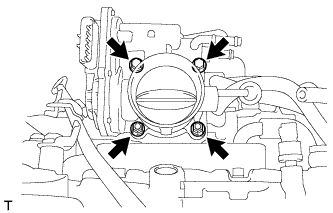
Install a new gasket and the diesel throttle body with the 2 bolts and 2 nuts.
- Torque:
- 11 N*m { 112 kgf*cm, 8 ft.*lbf }
-
Text in Illustration *1 No. 6 Water By-pass Hose *2 No. 7 Water By-pass Hose Connect the No. 6 and No. 7 water by-pass hoses.
-
-
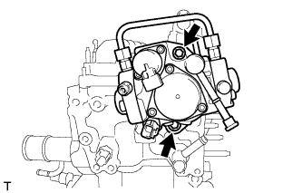
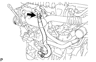
INSTALL VACUUM PUMP ASSEMBLY
-
Apply a light coat of engine oil to 2 new O-rings.
-
Install the 2 O-rings to the vacuum pump.
-
Install the vacuum pump with new 3 bolts.
- Torque:
- 21 N*m { 214 kgf*cm, 15 ft.*lbf }
-
Connect the vacuum hose.
-
-
INSTALL V-RIBBED BELT TENSIONER ASSEMBLY
-
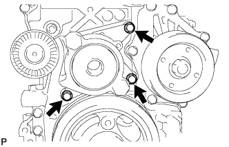
Install the belt tensioner with the 3 bolts.
- Torque:
- 20 N*m { 204 kgf*cm, 15 ft.*lbf }
Note
As the bolts' heads are not as thick as typical bolts, be careful not to damage them during installation.
-
-
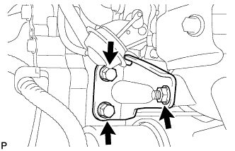
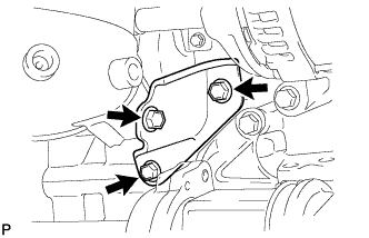
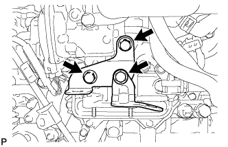
INSTALL ENGINE MOUNTING BRACKET
-
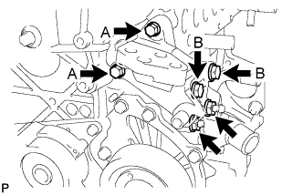
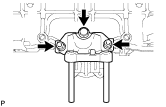
Set the mounting bracket on the engine.
-
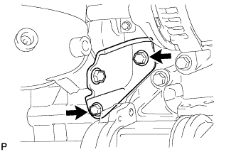
Temporarily install the 2 bolts labeled B and 2 nuts.
-
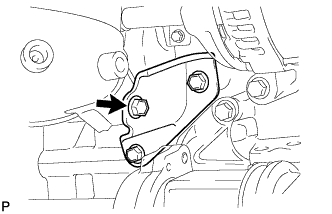
Install the 2 bolts labeled A.
- Torque:
- for bolt A
- 28 N*m { 286 kgf*cm, 21 ft.*lbf }
-
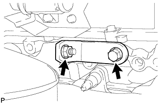
Tighten the 2 bolts labeled B and 2 nuts.
- Torque:
- for bolt B, nut
- 80 N*m { 816 kgf*cm, 59 ft.*lbf }
-
-
INSTALL NO. 4 WATER BY-PASS PIPE
-
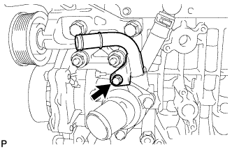
Install a new O-ring to the No. 4 water by-pass pipe.
-
Install the No. 4 water by-pass pipe with the bolt.
- Torque:
- 11 N*m { 112 kgf*cm, 8 ft.*lbf }
-
-
INSTALL NO. 1 IDLER PULLEY SUB-ASSEMBLY
-
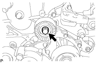
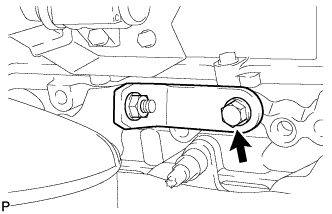
Install the idler pulley with the bolt.
- Torque:
- 40 N*m { 408 kgf*cm, 30 ft.*lbf }
-
-
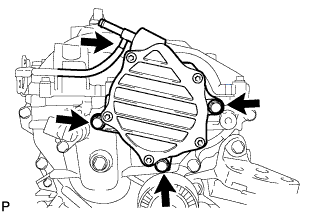
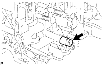
INSTALL IDLER PULLEY COVER PLATE
-
Install the idler pulley cover plate.
-
-
INSTALL NO. 2 IDLER PULLEY SUB-ASSEMBLY
-
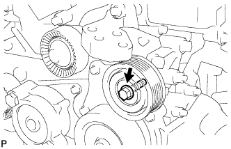
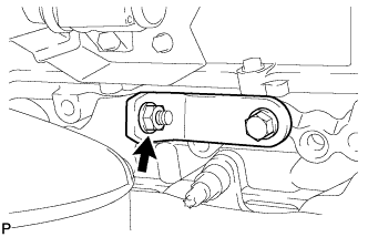
Install the idler pulley and plate with the bolt.
- Torque:
- 40 N*m { 408 kgf*cm, 30 ft.*lbf }
-
-
INSTALL GENERATOR ASSEMBLY
-
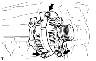
Install the generator with the 3 bolts.
- Torque:
- 25 N*m { 255 kgf*cm, 18 ft.*lbf }
-
-
INSTALL COMPRESSOR STAY
-
Install the compressor stay to the cylinder block.
- Torque:
- 35 N*m { 357 kgf*cm, 26 ft.*lbf }
-