CYLINDER BLOCK INSPECTION

-
INSPECT NO. 1 OIL NOZZLE SUB-ASSEMBLY
-
Check the oil nozzles for damage or clogging.
If there is damage or clogging, replace the oil nozzle.
-
-
CLEAN CYLINDER BLOCK SUB-ASSEMBLY
-
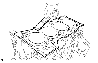
Using a gasket scraper, remove all the gasket material from the top surface of the cylinder block.
-
Using a soft brush and solvent, thoroughly clean the cylinder block.
-
-
INSPECT CYLINDER BLOCK FOR WARPAGE
-
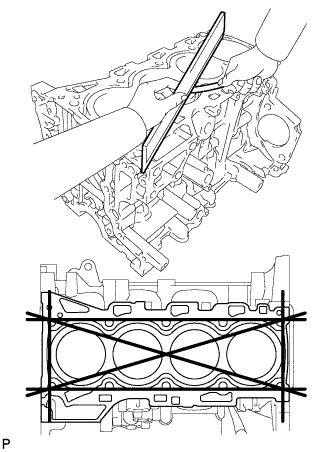
Using a precision straightedge and feeler gauge, measure the warpage of the surface where the cylinder head gasket contacts the cylinder head.
Maximum warpage 0.05 mm (0.00197 in.) If the warpage is more than the maximum, replace the cylinder block.
-
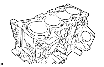
Visually check the cylinders for vertical scratches.
If deep scratches are present, replace the cylinder block.
-
-
INSPECT CYLINDER BORE
-
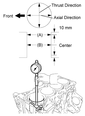
Using a cylinder gauge, measure the cylinder bore diameter at positions A and B in the thrust and axial directions.
Standard diameter 86.000 to 86.013 mm (3.3858 to 3.3863 in.) Maximum diameter 86.213 mm (3.3942 in.) If the diameter is more than the maximum, replace the cylinder block.
-
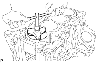
Inspect the cylinder ridge.
If the wear is less than 0.2 mm (0.00787 in.), using a ridge reamer, grind the top of the cylinder.
-
-
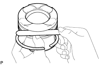
CLEAN PISTON
-
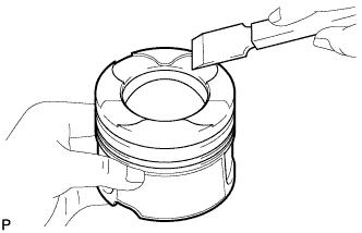
Using a gasket scraper, remove the carbon from the piston top.
-
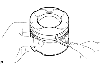
Using a groove cleaning tool or broken ring, clean the piston ring grooves.
-
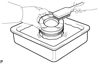
Using solvent and a brush, thoroughly clean the piston.
Note
Do not use a wire brush.
-
-
INSPECT PISTON DIAMETER
-
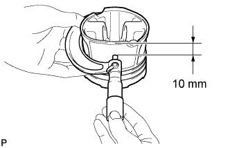
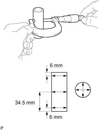
Using a micrometer, measure the piston diameter at right angles to the piston center line where the position is 10 mm (0.394 in.) from the bottom edge of the piston.
Standard piston diameter 85.919 to 85.933 mm (3.3826 to 3.3832 in.)
-
-
INSPECT PISTON OIL CLEARANCE
-
Measure the cylinder bore diameter in the thrust direction.
-
Subtract the piston diameter measurement from the cylinder bore diameter measurement.
Standard oil clearance 0.067 to 0.094 mm (0.00264 to 0.00370 in.) If the oil clearance is more than the standard, replace all the pistons. If necessary, replace the cylinder block.
-
-
INSPECT RING GROOVE CLEARANCE
-
Using a feeler gauge, measure the clearance between a new piston ring and the wall of the ring groove.
Ring Groove Clearance Ring Specified Condition No. 1 0.095 to 0.135 mm (0.00374 to 0.00531 in.) No. 2 0.08 to 0.12 mm (0.00315 to 0.00472 in.) Oil 0.03 to 0.07 mm (0.00118 to 0.00276 in.) If the clearance is more than the standard, replace the piston.
-
-
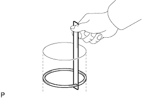
INSPECT PISTON RING END GAP
-
Insert the piston ring into the cylinder bore.
-
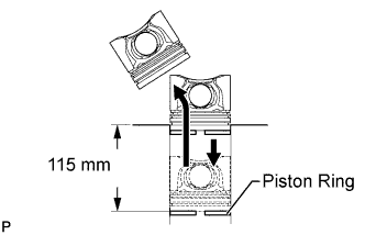
Using a piston, push the piston ring a little beyond the bottom of the ring travel 115 mm (4.53 in.) from the top of the cylinder block.
-
Using a feeler gauge, measure the end gap.
Standard End Gap Ring Specified Condition No. 1 0.22 to 0.32 mm (0.00866 to 0.0126 in.) No. 2 0.47 to 0.62 mm (0.0185 to 0.0244 in.) Oil 0.1 to 0.40 mm (0.00394 to 0.0157 in.) Maximum End Gap Ring Specified Condition No. 1 0.92 mm (0.0362 in.) No. 2 1.22 mm (0.0480 in.) Oil 1.00 mm (0.0394 in.) If the end gap is more than the maximum, replace the piston ring. If the end gap is more than the maximum even with a new piston ring, replace the cylinder block.
-
-
INSPECT PISTON PIN OIL CLEARANCE
-
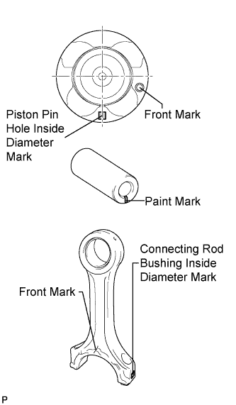
Check each mark on the piston, piston pin and connecting rod.
-
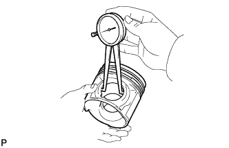
Using a caliper gauge, measure the inside diameter of the piston pin hole.
Standard Piston Pin Hole Inside Diameter Mark Specified Condition A 29.009 to 29.013 mm (1.1421 to 1.1422 in.) B 29.013 to 29.017 mm (1.1422 to 1.1424 in.) C 29.017 to 29.021 mm (1.1424 to 1.1426 in.) -
Using a micrometer, measure the piston pin diameter.
Piston Pin Diameter Mark (Paint Color) Specified Condition A (White) 29.000 to 29.004 mm (1.1417 to 1.1419 in.) B (Pink) 29.004 to 29.008 mm (1.1419 to 1.1420 in.) C (Blue) 29.008 to 29.012 mm (1.1420 to 1.1422 in.) -
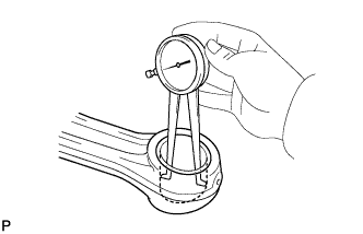
Using a caliper gauge, measure the inside diameter of the connecting rod bush.
Bush Inside Diameter Mark Specified Condition A 29.019 to 29.023 mm (1.1425 to 1.1426 in.) B 29.023 to 29.027 mm (1.1426 to 1.1428 in.) C 29.027 to 29.031 mm (1.1428 to 1.1430 in.) -
Subtract the piston pin diameter measurement from the piston pin hole diameter measurement.
Standard oil clearance 0.005 to 0.013 mm (0.000197 to 0.000512 in.) Maximum oil clearance 0.05 mm (0.00197 in.) If the oil clearance is more than the maximum, replace the connecting rod assembly. If necessary, replace the piston and piston pin as a set.
-
Subtract the piston pin diameter measurement from the bush inside diameter measurement.
Standard oil clearance 0.015 to 0.023 mm (0.000591 to 0.000906 in.) Maximum oil clearance 0.025 mm (0.000984 in.) If the oil clearance is more than the maximum, replace the connecting rod. If necessary, replace the connecting rod and piston pin as a set.
-
-
INSPECT CONNECTING ROD SUB-ASSEMBLY
-
Using a rod aligner and feeler gauge, check the connecting rod alignment.
-
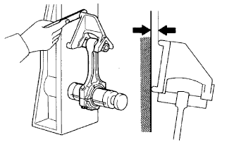
Check for bend.
Maximum bend 0.03 mm (0.00118 in.) per 100 mm (3.94 in.) If the bend is more than the maximum, replace the connecting rod sub-assembly.
-
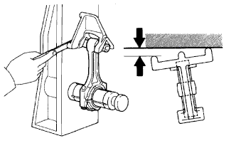
Check for twist.
Maximum twist 0.15 mm (0.00591 in.) per 100 mm (3.94 in.) If the twist is more than the maximum, replace the connecting rod sub-assembly.
-
-
-
INSPECT CONNECTING ROD THRUST CLEARANCE
-
Install the piston with pin, piston ring set and connecting rod bearing Click here.
-
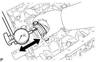
Using a dial indicator, measure the thrust clearance while moving the connecting rod back and forth.
Standard thrust clearance 0.10 to 0.45 mm (0.00394 to 0.0177 in.) Maximum thrust clearance 0.55 mm (0.0217 in.) If the thrust clearance is more than the maximum, replace one or more connecting rods as necessary. If necessary, replace the crankshaft.
-
Remove the connecting rod bearing, piston ring set and piston with pin Click here.
-
-
INSPECT CONNECTING ROD OIL CLEARANCE
-
Install the connecting rod bearing Click here.
-
Install the crankshaft bearing Click here.
-
Install the upper crankshaft thrust washer Click here.
-
Install the crankshaft Click here.
-
Clean the crank pin and connecting rod bearing.
-
Check the crank pin and connecting rod bearing for pitting and scratches.
-
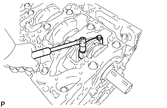
Install the connecting rod.
-
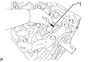
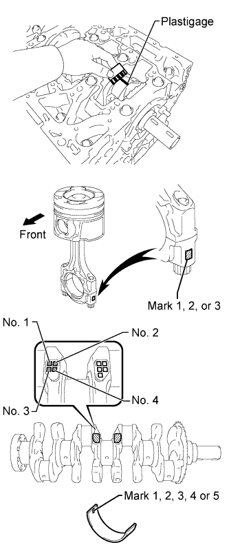
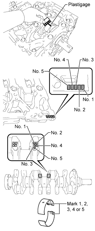
Text in Illustration *1 Plastigage Lay a strip of Plastigage on the crank pin.
-
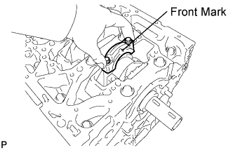
Check that the front mark (protrusion) of the connecting rod cap is facing forward and install the cap.
-
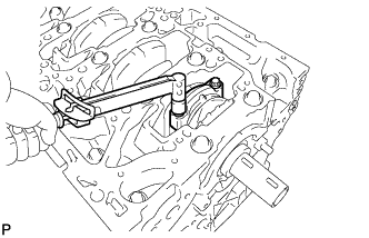
Install and alternately tighten the bolts of the connecting rod cap in several steps.
- Torque:
- 40 N*m { 408 kgf*cm, 30 ft.*lbf }
Note
Do not turn the crankshaft.
-
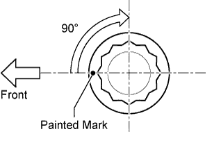
Mark the front side of each connecting cap bolt with paint.
-
Tighten the cap bolts by 90°.
-
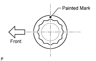
Check that the painted marks are now at a 90° angle to the front.
Note
Do not turn the crankshaft.
-
Remove the 2 connecting rod cap bolts.
-
Using the 2 removed connecting rod cap bolts, remove the connecting rod cap and lower bearing by wiggling the connecting rod cap right and left.
Tech Tips
Keep the lower bearing inserted to the connecting rod cap.
-
Measure the Plastigage at its widest point.
Standard oil clearance 0.024 to 0.042 mm (0.000945 to 0.00165 in.) Maximum oil clearance 0.070 mm (0.00276 in.) If the oil clearance is more than the maximum, replace the bearings. If necessary, replace the crankshaft.
Tech Tips
If using a standard bearing, replace it with one that has the same number. If the number of the bearing cannot be determined, select the correct bearing by adding together the numbers imprinted on the crankshaft and connecting rod, then selecting the bearing with the same number as the total. There are 5 sizes of standard bearings, marked 1, 2, 3, 4 and 5.
Standard Bearing Chart Item Number Mark Connecting rod cap 3 2 3 1 2 3 1 2 1 Crankshaft 2 2 1 2 1 0 1 0 0 Use bearing 5 4 3 2 1 EXAMPLE:
Connecting rod cap "3" + Crankshaft "1" = Total number 4 (Use bearing "4")
Reference Connecting Rod Big End Inside Diameter Mark Specified Condition 1 53.000 to 53.006 mm (2.0866 to 2.0869 in.) 2 53.006 to 53.012 mm (2.0869 to 2.0871 in.) 3 53.012 to 53.018 mm (2.0871 to 2.0873 in.) Crankshaft Pin Diameter Mark Specified Condition 0 49.994 to 50.000 mm (1.9683 to 1.9685 in.) 1 49.988 to 49.994 mm (1.9680 to 1.9683 in.) 2 49.982 to 49.988 mm (1.9678 to 1.9680 in.) Standard Sized Bearing Center Wall Thickness Mark Specified Condition 1 1.485 to 1.488 mm (0.0585 to 0.0586 in.) 2 1.488 to 1.491 mm (0.0586 to 0.0587 in.) 3 1.491 to 1.494 mm (0.0587 to 0.0588 in.) 4 1.494 to 1.497 mm (0.0588 to 0.0589 in.) 5 1.497 to 1.500 mm (0.0589 to 0.0591 in.) -
Completely remove the Plastigage.
-
Remove the connecting rod.
-
Remove the crankshaft Click here.
-
Remove the upper crankshaft thrust washer Click here.
-
Remove the crankshaft bearing Click here.
-
Remove the connecting rod bearing Click here.
-
-
INSPECT CONNECTING ROD BOLT
-
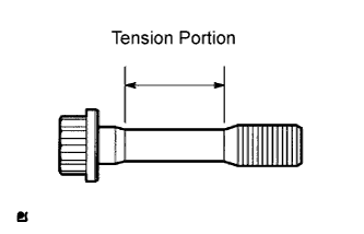
Using a vernier caliper, measure the tension portion diameter of the bolt.
Standard diameter 8.7 to 8.8 mm (0.343 to 0.346 in.) Minimum diameter 8.5 mm (0.335 in.) If the diameter is less than the minimum, replace the bolt.
-
-
INSPECT CRANKSHAFT
-
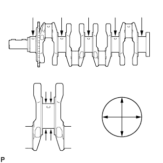
Inspect for circle runout.
-
Place the crankshaft on V-blocks.
-
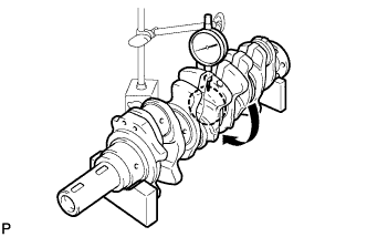
Using a dial indicator, measure the circle runout at the center journal.
Maximum circle runout 0.04 mm (0.00157 in.) If the circle runout is more than the maximum, replace the crankshaft.
-
-
Inspect the main journals.
-
Using a micrometer, measure the diameter of each main journal.
Standard journal diameter 58.982 to 59.000 mm (2.3221 to 2.3228 in.) If the diameter is not as specified, check the oil clearance. If necessary, replace the crankshaft.
-
Check each main journal for taper and out-of- round.
Maximum taper and out-of-round 0.005 mm (0.000197 in.) If the taper and out-of-round is more than the maximum, replace the crankshaft.
-
-
Inspect the crank pin.
-
Using a micrometer, measure the diameter of each crank pin.
Standard crank pin diameter 49.982 to 50.000 mm (1.9678 to 1.9685 in.) If the diameter is not as specified, check the oil clearance. If necessary, replace the crankshaft.
-
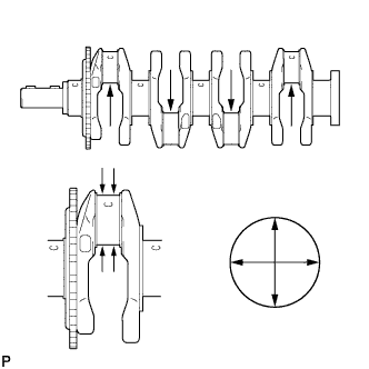
Check each crank pin for taper and out-of-round.
Maximum taper and out-of-round 0.003 mm (0.000118 in.) If the taper and out-of-round is more than the maximum, replace the crankshaft.
-
-
-
INSPECT CRANKSHAFT THRUST CLEARANCE
-
Install the crankshaft bearing, upper crankshaft thrust washer and crankshaft Click here.
-
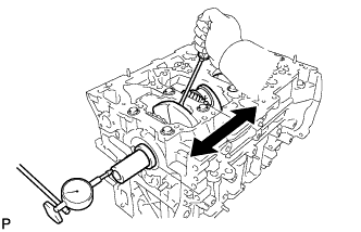
Using a dial indicator, measure the thrust clearance while prying the crankshaft back and forth with a screwdriver.
Standard thrust clearance 0.04 to 0.24 mm (0.00157 to 0.00945 in.) Maximum thrust clearance 0.30 mm (0.0118 in.) If the thrust clearance is more than the maximum, replace the thrust washers as a set. If necessary, replace the crankshaft.
Standard thrust washer thickness 1.93 to 1.98 mm (0.0760 to 0.0780 in.) -
Remove the crankshaft, upper crankshaft thrust washer and crankshaft bearing Click here.
-
-
INSPECT CRANKSHAFT OIL CLEARANCE
-
Install the crankshaft bearing Click here.
-
Install the upper crankshaft thrust washer Click here.
-
Clean each main journal and bearing.
-
Check each main journal and bearing for pitting and scratches.
Tech Tips
If the journal or bearing is damaged, replace the bearing.
-
Place the crankshaft on the cylinder block.
-
Text in Illustration *1 Plastigage Lay a strip of Plastigage across each journal.
-
Place the crankshaft bearing cap assembly on the cylinder block.
-
Temporarily install the crankshaft bearing cap bolts.
Tech Tips
The main bearing cap bolts are tightened in 2 progressive steps.
-
Step 1:
-
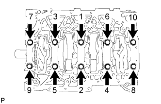
Uniformly tighten the 10 main bearing cap bolts in several passes, in the sequence shown in the illustration.
- Torque:
- 60 N*m { 612 kgf*cm, 44 ft.*lbf }
Tech Tips
If any of the main bearing cap bolts does not meet the torque specification, replace the main bearing cap bolt.
Note
Do not turn the crankshaft.
-
-
Step 2:
-
Mark the front of the bearing cap bolts with paint.
-
Tighten the bearing cap bolts by 90° as shown.
-
Check that the painted marks are now at a 90° angle to the front.
-
-
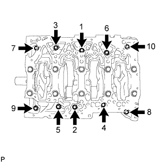
Install and uniformly tighten the 10 bolts in several passes, in the sequence shown in the illustration.
- Torque:
- 18 N*m { 184 kgf*cm, 13 ft.*lbf }
-
Remove the crankshaft bearing cap.
-
Measure the Plastigage at its widest point.
Standard Oil Clearance Journal Specified Condition No. 3 0.020 to 0.038 mm (0.000787 to 0.00150 in.) Others 0.014 to 0.032 mm (0.000551 to 0.00126 in.) Maximum oil clearance 0.10 mm (0.00394 in.) If the oil clearance is more than the maximum, replace the bearings. If necessary, replace the crankshaft.
Tech Tips
If using a standard bearing, replace it with one having the same number. If the number of the bearing cannot be determined, select the correct bearing by adding together the numbers imprinted on the cylinder block and crankshaft, then selecting the bearing with the same number as the total.
There are 6 sizes of standard bearings, marked 0, 1, 2, 3, 4 and 5.
Standard Bearing Chart No. 3 Journal Item Number Mark Cylinder block 2 2 1 2 1 0 1 0 0 Crankshaft 2 1 2 0 1 2 0 1 0 Use bearing 4 3 2 1 0 Other Journals Item Number Mark Cylinder block 3 3 2 3 2 1 2 1 1 Crankshaft 2 1 2 0 1 2 0 1 0 Use bearing 5 4 3 2 1 EXAMPLE:
Cylinder block "2" + Crankshaft "1" = Total number 3 (Use bearing "3")
Reference Standard Cylinder Block Main Journal Bore Diameter No. 3 Journal Mark Specified Condition 0 63.000 to 63.006 mm (2.4803 to 2.4805 in.) 1 63.006 to 63.012 mm (2.4805 to 2.4808 in.) 2 63.012 to 63.018 mm (2.4808 to 2.4810 in.) Other Journals Mark Specified Condition 1 63.000 to 63.006 mm (2.4803 to 2.4805 in.) 2 63.006 to 63.012 mm (2.4805 to 2.4808 in.) 3 63.012 to 63.018 mm (2.4808 to 2.4810 in.) Standard Crankshaft Journal Diameter Mark Specified Condition 0 58.994 to 59.000 mm (2.3226 to 2.3228 in.) 1 58.988 to 58.994 mm (2.3224 to 2.3226 in.) 2 58.982 to 58.988 mm (2.3221 to 2.3224 in.) Standard Sized Bearing Center Wall Thickness Mark Specified Condition 0 1.987 to 1.990 mm (0.0782 to 0.0783 in.) 1 1.990 to 1.993 mm (0.0783 to 0.0785 in.) 2 1.993 to 1.996 mm (0.0785 to 0.0786 in.) 3 1.996 to 1.999 mm (0.0786 to 0.0787 in.) 4 1.999 to 2.002 mm (0.0787 to 0.0788 in.) 5 2.002 to 2.005 mm (0.0788 to 0.0789 in.) -
Completely remove the Plastigage.
-
Lift out the crankshaft.
-
Remove the upper crankshaft thrust washer Click here.
-
Remove the crankshaft bearing Click here.
-
-
INSPECT CRANKSHAFT BEARING CAP SET BOLT
-
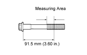
Using a vernier caliper, measure the thread outside diameter of the crankshaft bearing cap set bolt.
Standard diameter 10.8 to 11.0 mm (0.425 to 0.433 in.) Minimum diameter 10.4 mm (0.409 in.) If the diameter is less than the minimum, replace the bolt.
-